Precision Model Resin and Form 4B: Guide to Making the Most Accurate Restorative Dental Models
Formlabs' Form 4B dental 3D printer is a game-changer for printing restorative dental models. It features fast printing speeds, reliability, and consistently precise outputs. This article is a guide on how to easily make functional and accurate restorative dental models on Form 4B with Precision Model Resin.
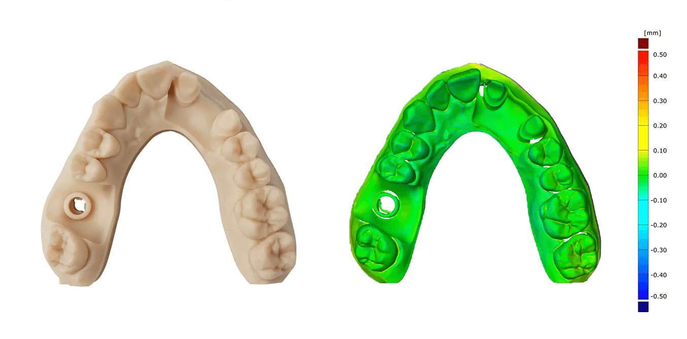
Precision Model Resin can achieve the highest accuracy out of any resin in the Formlabs resin library. It delivers an excellent surface finish and provides accuracy with a trueness of +/- 100 µm on over 99% of surfaces, and a trueness of +/- 50 µm on about 95% of surfaces. The resin's neutral, eye-friendly color and opacity are ideal for spotting small anatomical details and make it easy to scan with dental scanners.
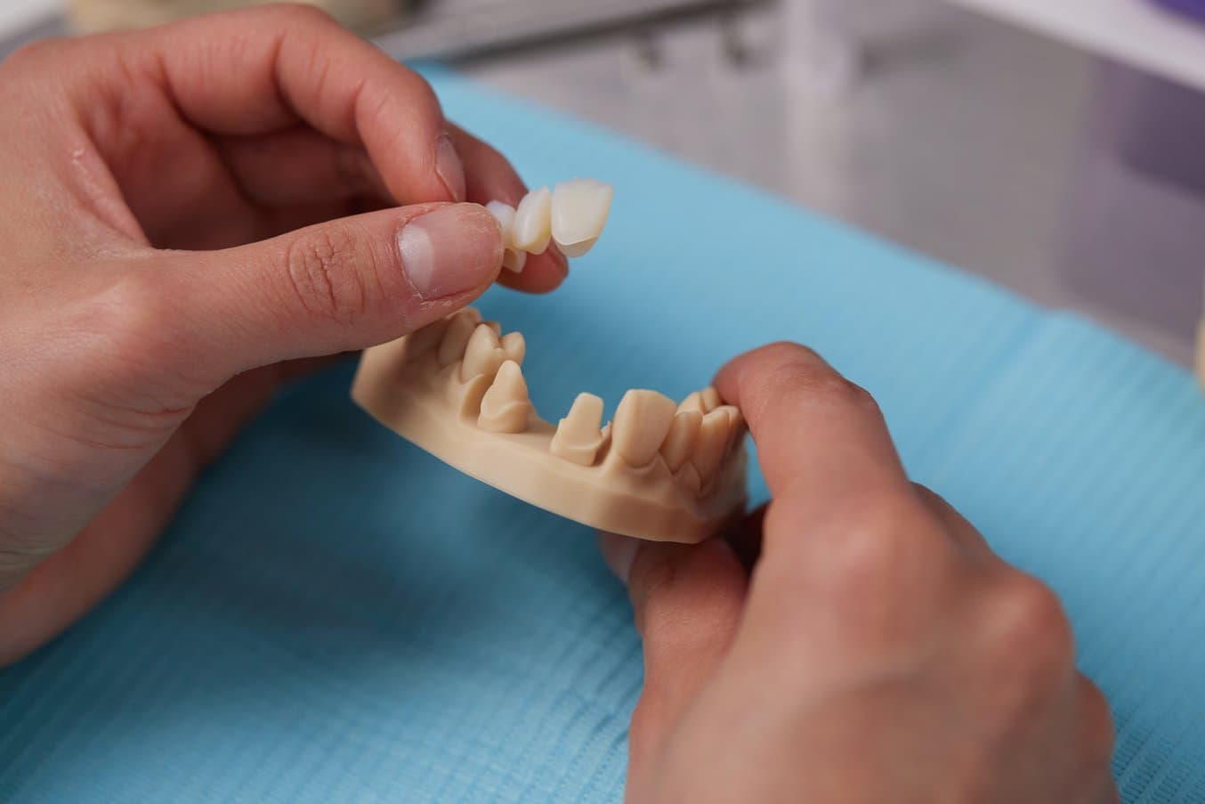
Table of Contents
Precision Model Resin and Form 4B: Guide to Making the Most Accurate Restorative Dental Models
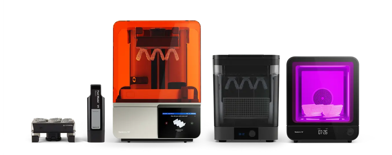
Required Hardware and Materials
Made by Formlabs:
- Form 4B 3D Printer
- Form 4 Resin Tank and Form 4 Mixer
- Form 4 Build Platform or Form 4 Build Platform Flex
- Precision Model Resin
- Form Wash
- Formlabs validated curing unit: Form Cure, Form Cure L, or Fast Cure
- Form 4 Finishing Kit or secondary wash station
Made by Third Parties:
- Cutting and finishing tools:
- Dry lubricant powder (talcum / baby powder / PTFE powder) (highly recommended)
- Sandpaper (recommended)
- Soft brush (recommended)
- Tool for pushing die out (recommended)
- Various burrs for removing excess resin and touchpoints of supports (adapt to your own preferences)
- Occlusion paper (optional)
- Desktop scanner (if physical impression or model)
Required Software
Made by Formlabs:
-
PreForm Dental Software (free) 3.37 or higher
-
Form 4B 3D Printer Firmware 1.4.0 or higher - Learn more
Made by Third Parties:
Dental design software such as 3Shape or exocad
1. 3D Printed Precision Model Resin Dental Models Meet the Requirements for Restorative Applications
Accuracy in printed models forms the foundation for subsequent restoration work. Any errors in the models can directly impact the precision of the restorations.
Restorative models, in particular, demand the highest level of accuracy, unlike models used for thermoforming or similar applications. Accuracy is widely recognized as more critical than speed and reliability. Formlabs’ Form 4B 3D printer, used with Precision Model Resin, excels by delivering high accuracy, speed, and reliability, effectively meeting these three requirements.
In a detailed assessment comparing the accuracy of plaster models and 3D printed models made with Precision Model Resin, we found that 3D printed models are comparable to traditional methods due to the accuracy of the Form 4B and the accuracy of Precision Model Resin. Learn more about how this accuracy calculation was conducted for Precision Model Resin here.
Accuracy of Precision Model Resin
| Formlabs Precision Model Resin printed on Form 4B | Comparator #1 DentaModel printed on Asiga UV Max | Comparator #2 Die and Model 2 printed on SprintRay | |
|---|---|---|---|
| +/- 100 μm tolerance | 99.9 | 99.7 | 90.4 |
| +/- 50 μm tolerance | 97.4 | 91.3 | 62.0 |
| +/- 25 μm tolerance | 75.7 | 62.8 | - |
Note: Parts printed at 50 μm layer height.
CAD Design Considerations
In the traditional workflow, one of the most common types of models is the Splitcast type, where an arch is coupled with a base plate and cut into sections to allow the technician to remove the die for manual adjustments. Less common are models without the section cuts, where dies are inserted into a slot of the plaster model. These are often known as “alveolar models” and represent a substantial amount of extra work and skills.
As this second type of model, the “alveolar model,” is much easier to design in CAD software, this type of design represents the majority of 3D printed models. The following guidelines apply to this type of model. Formlabs provides presets for printing this type of restorative model.
After obtaining a digital model of a patient’s dentition, either based on a plaster model or intraoral scan, these files (STL, PLY, OBJ) can be imported into a dental CAD model software for design.
Configuration options available for plateless models* in CAD model software:
-
Structure: Models can be either solid or hollow.
-
Dies: Options include designs with removable dies or fixed preparations, with the option to add extra dies as needed. See below for Formlabs guidelines on removable dies.
-
Geometry:
-
3Shape: Typically features square-shaped dies with slight conicity and friction bars, enhancing fit and placement by default.
-
exocad: Defaults to parallel-walled dies that closely follow the margin line for a consistent fit.
-
-
Additional Options:
-
Both 3Shape and exocad support ejection pins and control holes, which are used for visual confirmation of proper seating.
-
Both 3Shape and exocad support conical die shapes for easy insertion.
-
*We differentiate between plateless (similar to the above-mentioned “alveolar model”) and plate models with cut sections. Plate models are not well suited for 3D printing due to their positioning geometry on the bottom of the model base.
Print Arches Directly on the Build Platform
We recommend printing directly on the build platform to take advantage of its benefits:
-
Support and Accuracy: The build platform provides the best support structure available in 3D printing, leading to the highest accuracy due to stable printing conditions.
-
Efficiency: With the model parallel to the build platform, there is no need for a raft or additional support structures. This results in fewer layers to print, which not only speeds up the printing process, but also reduces resin consumption.
Printing a model directly on the build platform is considered best practice, however, when paired with removable dies or implant analog slots, it can result in suction cups in your 3D print.
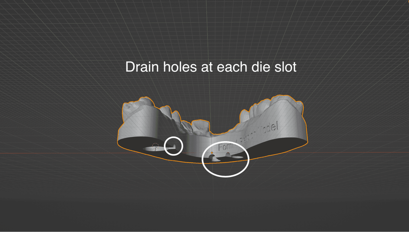
How To Avoid Suction Cups With Drain Holes
A suction cup in 3D printing is an area where resin cannot flow freely because it is enclosed by the model walls. This occurs in features like removable die slots, implant analog slots, or due to the model's shape.* The movement of the build platform during printing creates a pump effect, pressurizing and depressurizing the trapped resin, which can negatively impact accuracy.
By adding drain holes, this pressurization effect is neutralized, enhancing the print's accuracy. While Form 4B is less prone to accuracy loss or severe print issues, adding holes at each slot at the base level of the model remains the best practice. Both 3Shape and exocad have options for drain holes in their modeling software, and detailed instructions are available here.
For implant analog slots, we highly recommended that drain holes be added. In addition to eliminating suction cups, a hole at the implant analog slot will enable you to visually inspect the proper seating of the analog. In this case, both for exocad and 3Shape, these holes need to be designed manually.
*Hollow models are not recommended for maintaining the highest accuracy. However, when printing hollow, drain holes are crucial to avoiding suction cups and minimize distortion.
Removable Dies Guidelines
In this section, we provide guidelines on removable die design configurations available in CAD design software and compatibility with Formlabs Precision Model Resin.
-
We recommend removable dies be printed on supports.
-
The step-by-step section of this guide provides a detailed walkthrough.
-
Formlabs offers presets, which provide tested and well-working presets for exocad and 3Shape design software.
The image on the right represents the presets provided by Formlabs, each lacking a pin and boasting an organic and slightly conical shape for easy insertion.
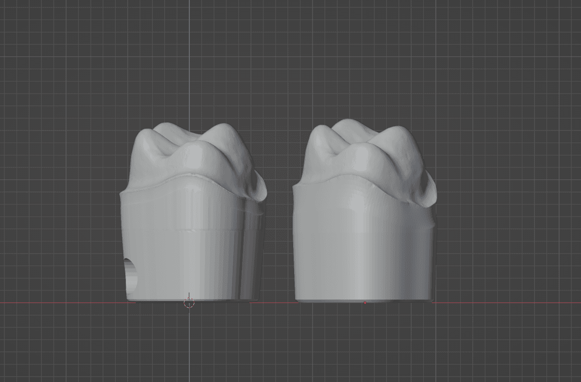
Dies produced with Formlabs presets side by side. 3Shape die on the left, exocad die on the right.
Conical vs. Parallel Wall Dies
-
Conical dies are easier to insert and user-friendly, although they may present challenges in achieving a tight fit.
- Parallel walls provide even friction along the die, improving stability, but can be more difficult to insert and pose a risk of misalignment.
Pin or No Pin
Many dental model software packages commonly include an option to add an ejection pin at the bottom of the die. When necessary, this pin helps push the die out of the model. While these pins can be very useful, the use of a pin can impact your print setup, including:
-
The orientation on the build platform
-
The need for proper support structures (detailed instructions in the step-by-step section)
Additionally, with small dies, such as a lower central, the pin can become as thin as a needle.
Formlabs presets do not include the pin by default. You will have the option to add ejection pins in your settings if you prefer. When using ejection pins, we recommend a height of 1 mm. Taller pins may reduce the length of the friction area.
Setting an Ideal Model Height
While minimizing model height can help save resin and print time, it can negatively impact obtaining a secure fit of removable dies. We recommend a base height of 15-18 mm at the lowest section of the soft tissue part, excluding the teeth, for the best fit.
Friction between the die and model is a primary factor in obtaining a tight and secure fit of removable dies. Given that the contact surface, or friction surface, between the dies and model begins below the lowest point of the margin line, the height of the model becomes important in dictating how much friction surface is available. This is particularly important for anterior teeth, where the margin line is often lower on the vestibular side than on the lingual side, relative to the model base. This results in a shorter friction surface.
If dies are too loose or not securely locked in place, increasing the height of the model, and thus increasing the length of the dies’ insertion path, can be beneficial.
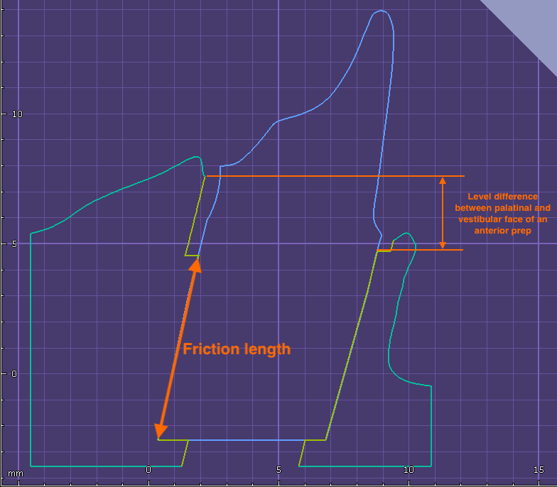
Cross-section of an anterior die.
Angulated Dies
The insertion axis of a removable die can be restricted by the patient's anatomy. Ideally, the die should be perpendicular to the model base, ensuring the smoothest surface and optimal friction. However, patient anatomy may require adjusting the insertion axis away from the model's Z axis.
We recommend limiting this angulation to 15°, if possible. Larger angles will create more pronounced layer steps in the die slot, increasing friction.
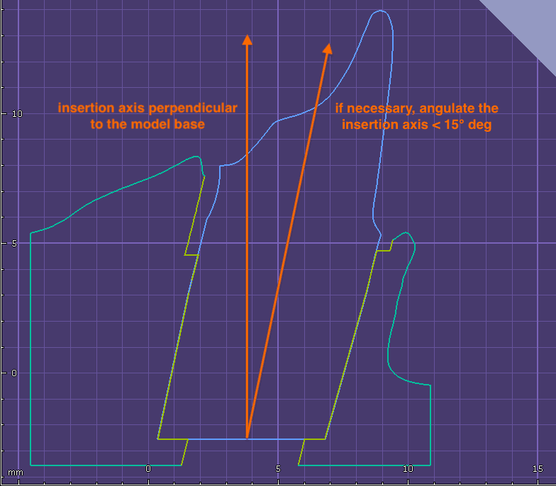
Angulated Die
Implant Model Design Guidelines
Implant models are a special case in model design requiring high accuracy and a high degree of fit.
Below we provide guidelines to maximize fit when designing implant models for 3D printing with Formlabs Precision Model Resin.
Types of Implant Analogs
Implant analogs for 3D printed models are different from analogs for plaster models. With plaster models, the plaster is poured around the analog, whereas with 3D printed models, the analog is inserted into the model after it is printed. For this purpose, implant and third-party manufacturers provide analogs of two types. The most important requirement for the implant model is that the analog can be inserted and locked into the correct position.
Screw-Type Analogs
This type of analog has threading at the bottom, allowing the analog to be fixed in the model by a counter screw/nut accessible from underneath the model, e.g., NT-Trading analogs, DESS analogs.
Click-In Type Analogs
This type of analog needs to be pushed into its location and snapped over a positive or negative retention feature to fix it into position, e.g., Camlog OEM analogs, Medentika analogs.
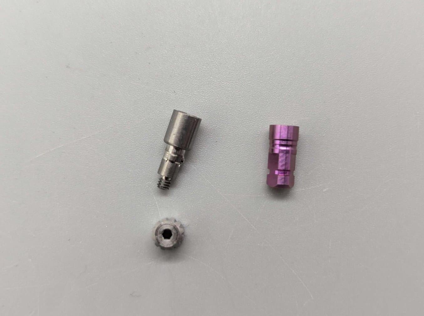
A screw-type analog from NT Trading (left) and click-in type analog from Camlog (right).
Recommended Analog-to-Model Offsets
Formlabs provides offsets for click-in type analogs as part of the Precision Model Resin libraries for exocad and 3Shape.
| Offset | Friction bar overlap | ||
|---|---|---|---|
| exocad | Click-in type | 0.060 mm | N/A |
| Screw-type | 0.010 mm | N/A | |
| 3Shape | Click-in type | 0.060 mm | 0.010 mm |
| Screw-type | 0.010 mm | 0.010 mm |
Note that the offset for screw-type analogs is different from click-in type analogs. This may require an adjustment in your CAD software.
Adjustments of analog-to-model offsets are available in 3Shape Model Builder and in exocad Model Creator.
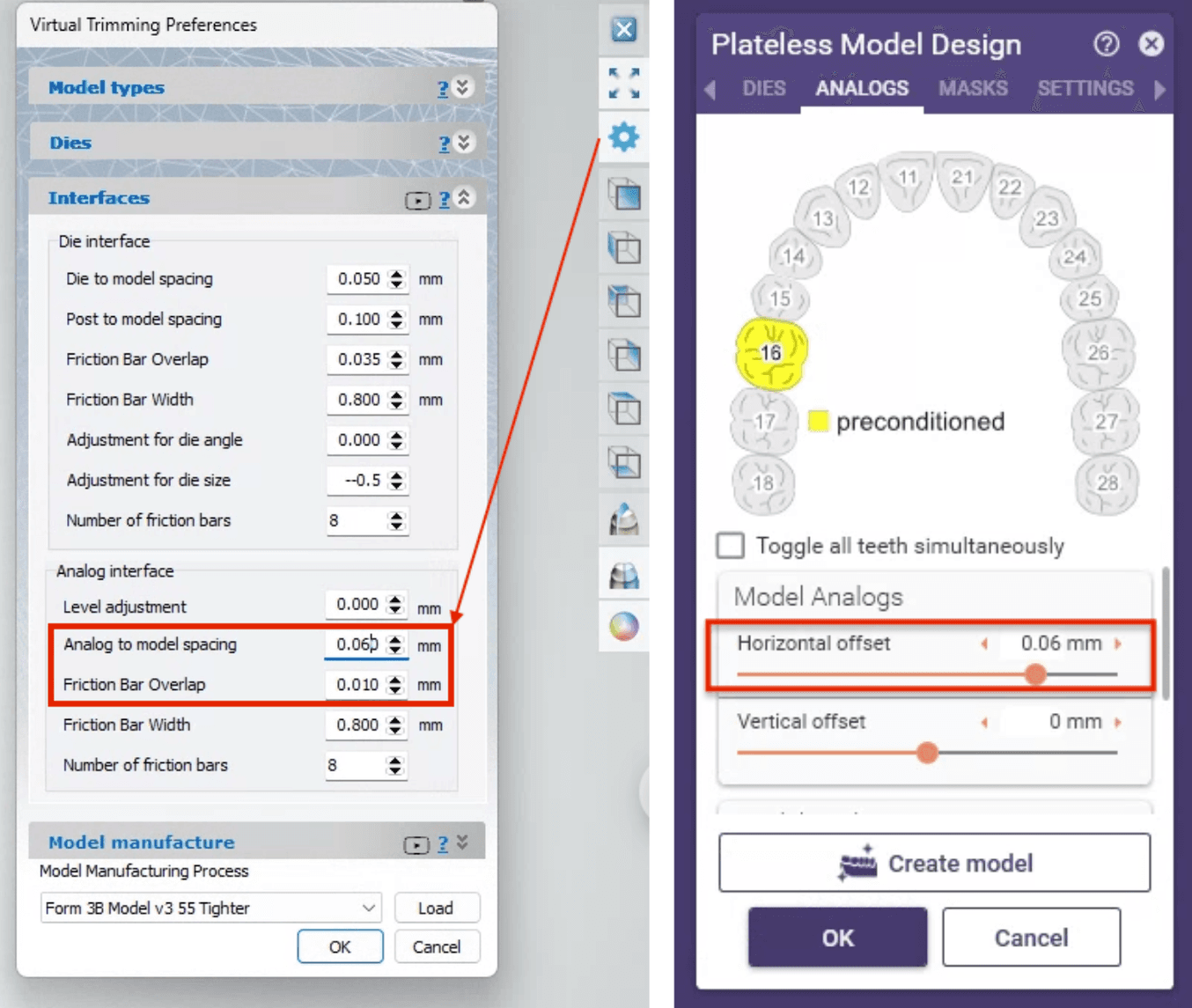
Left: Analog-to-model offset adjustment in 3Shape Model Builder. Right: Horizontal offset of model analogs in exocad Model Creator.
2. CAD Libraries and How To Install
Download Library for exocad and 3Shape
How To Install
exocad
1. The exocad file comes in a zip folder. Extract the files from the zip folder.
2. Place the settings file “FORMLABS Form 4B Precision Model.XML” into [your exocad installation path]/DentalCADApp/library/production
3. Place the settings folder “FORMLABS Form 4 Plateless Model” into [your exocad installation path]/DentalCADApp/library/modelcreator/plates
3Shape
The 3Shape DME file should be imported into your system using the Control Panel Application.
Other Software Packages
The general design recommendations can be easily adapted to other model design software for which we do not provide native libraries. Here is a summary of the main settings for removable dies that should work with Precision Model Resin:
| Summary of Removable Die Settings | |
|---|---|
| Model / die offset | 0.000 to - 0.015 mm |
| Recommend die slot depth | ≥ 15 mm |
| Maximum angulation recommended | +/- 15° from Z axis |
| Taper if applicable | 2° |
| Implant Analog-to-Model Offsets | See the "Recommended Analog-to-Model Offsets" section |
3. Step-By-Step: Restorative Model Prints in PreForm
3.1 Setting up Your Print
Learn how to start using PreForm Dental here.
-
We recommend printing models directly on the build platform and ensuring every removable die slot or implant analog slot has a draining hole.
-
For the best results, dies should be manually oriented and supported. Learn how to manually set up prints in PreForm Dental here.
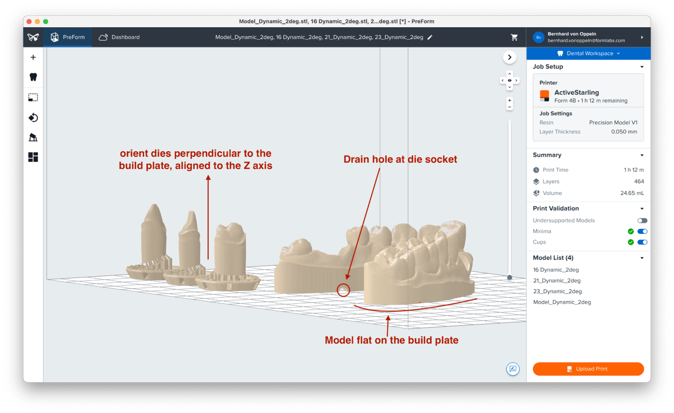
Ideal setup for a die (with or without a pin):
-
Align the die to the Z axis, ensuring it is perpendicular to the build platform for smooth and consistent die walls.
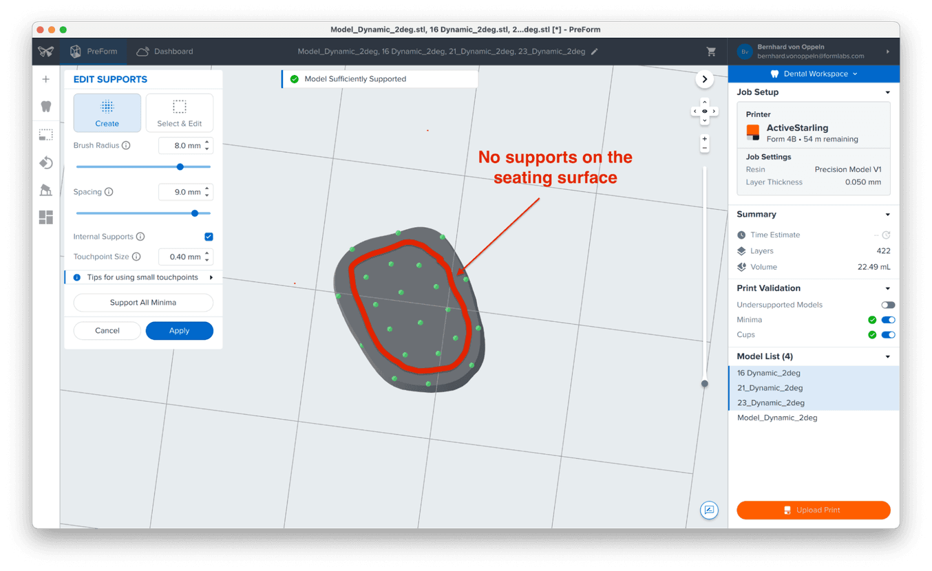
-
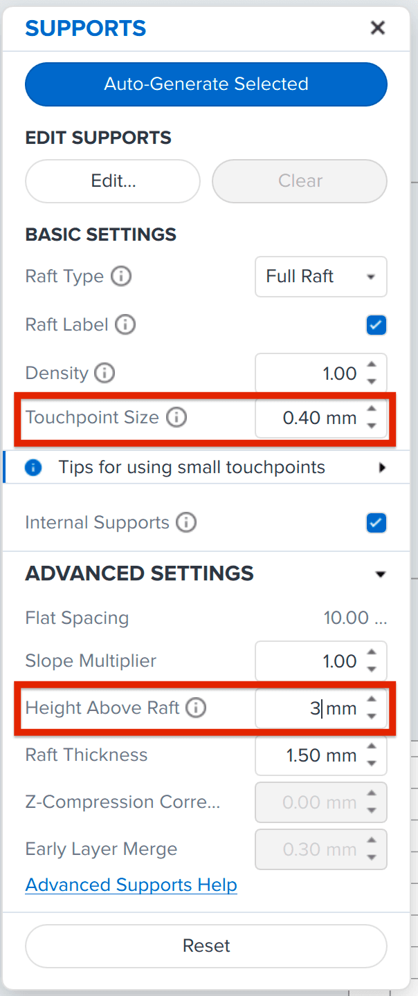
Edit supports manually:
-
Decrease touchpoint size to 0.4 mm for easier finishing.
-
Decrease height above raft to 3 mm to enhance stability.
-
Avoid placing supports on the seating surface. Keep supports approximately 1 mm from the outer boundary of the die’s bottom. Refer to the image below.
-
3.2 After Printing: How to Post-Process Your Models
The post-processing recommendations for Precision Model Resin are:
| Washing | 5 min in the Form Wash |
|---|---|
| Drying | 30 min dry time on the bench or blow dry with compressed air after taking parts out of the wash and then let dry for an additional 15 min |
| Curing | 5 min at 35 °C in the Form Cure or 30 sec at Intensity 2 in the Fast Cure |
Dos and Don’ts When Post-Processing
-
Never use brushes or other tools for cleaning. When parts come out of the Form Wash, they are soft, and you might lose accuracy for the model and, more importantly, on the die fit.
-
If you have access to compressed air for blow-drying the parts after washing, blow-dry parts immediately after taking them out of the wash while the parts are still wet. This prevents dissolved resin residue in the IPA from settling on the objects and affecting accuracy.
For Best Results: Use a Two-Step Wash Procedure
-
With every wash cycle, more resin residue gets dissolved in the IPA. This residue can affect accuracy on critical parts such as dies, die slots, and analog slots.
-
To prevent this from happening, you can use a two-step wash cycle:
-
Wash #1 with used IPA for 3 min
-
Wash #2 with fresh IPA for 2 min, or 2 min in an ultrasonic bath with clean IPA
-
Bench Dry or Compressed Air?
Using compressed air immediately after taking the parts out of the Form Wash helps to prevent any resin residue from settling on critical parts and shortens the required dry time before curing.
3.3 Finishing the Printed Parts
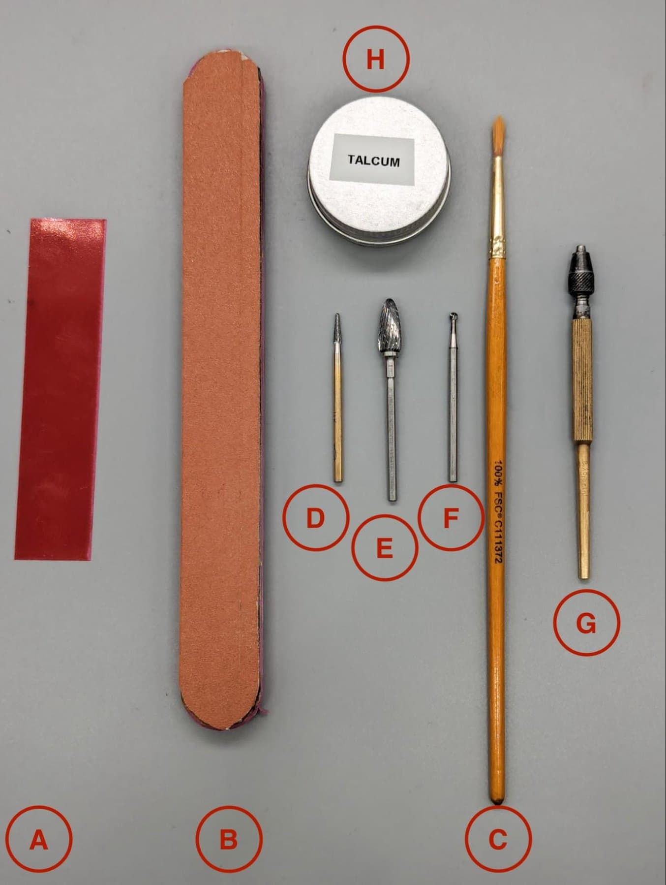
Recommended Tools
| A | Occlusion paper (optional) |
|---|---|
| B | Sandpaper (recommended) |
| C | Soft brush (recommended) |
| D, E, F | Various burs for removing excess resin and touchpoints of supports (adapt to your own preferences) |
| G | Tool for pushing die out (recommended) |
| H | Dry lubricant powder (talcum / baby powder / PTFE powder) (highly recommended) |
Best Practices
Remove touch points. Do not touch the seating area. The seating area in 3Shape or exocad has an average width of 1 mm. You can be more aggressive with removing material from the inner non-seating area for a better die fit, but try to be very delicate at the outer edge as it is directly connected to the seating area.
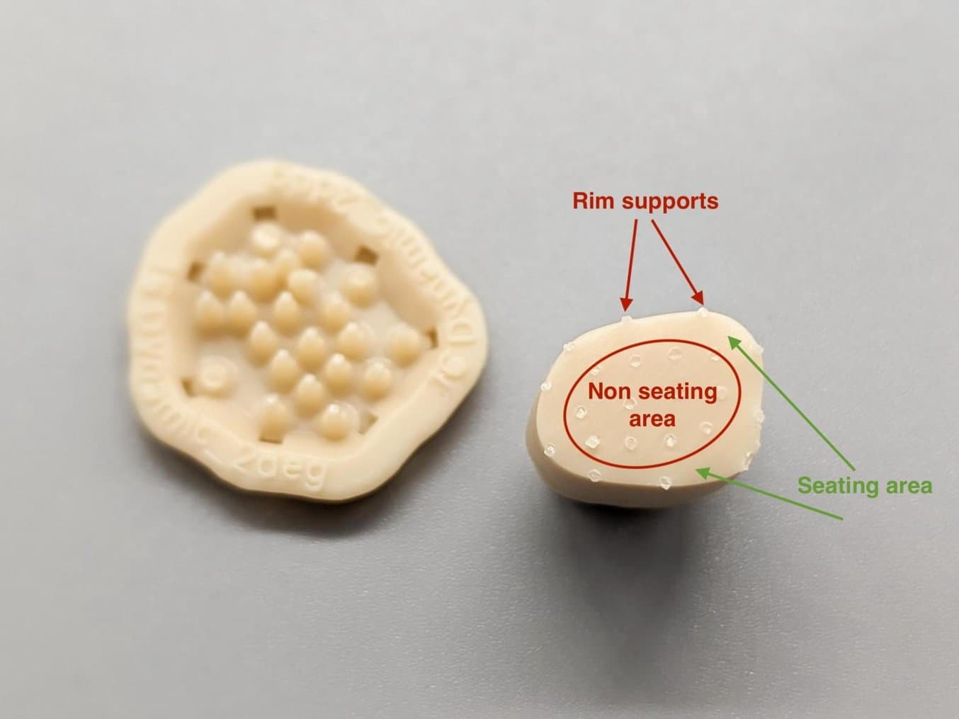
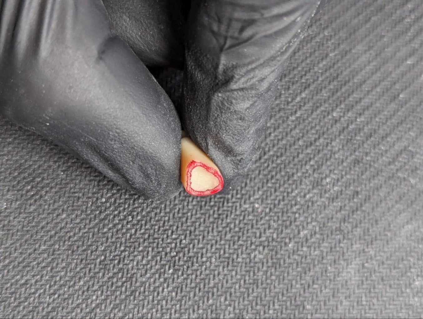
Illustration of an adjusted die bottom for optimal fit. Notice that the inner non-seating area was hollowed for better seating. We used occlusion paper to illustrate the untouched seating area. This is a technique that can be very helpful when learning how to make removable dies.
Assembly
Assembling the dies and the model should be done carefully. Find the exact position, rotation, and insertion axis before starting to push the die down. Our presets are relatively tight to achieve a good position lock.
We highly recommend using a dry lubricant to decrease friction and protect the die surfaces from wear and abrasion. The most affordable dry lubricant is talcum / baby powder. Avoid spray-on dry lubricants, as the propellant of spray cans can soften the resin.
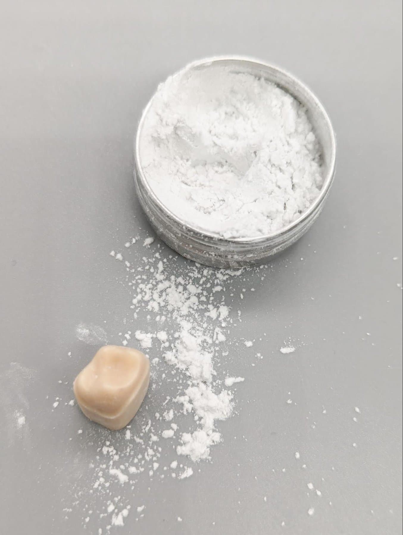
Use talcum for easier insertion and protection of the die.
3.4 What if My Die Is Too Tight or Too Loose?
Formlabs provides a validated set of working removable die settings for ease of use and consistency. However, it is also possible to adjust these settings to individualize the fit for your application. See below how to modify the settings:
| Die is too loose | Decrease the horizontal gap in your model design by 10 µm. Example: Actual die gap = 0.000 mm New die gap = -0.010 mm |
| Die is too tight | Increase the horizontal gap in your model design by 10 µm. Example: Actual die gap = 0.000 mm New die gap = 0.010 mm |
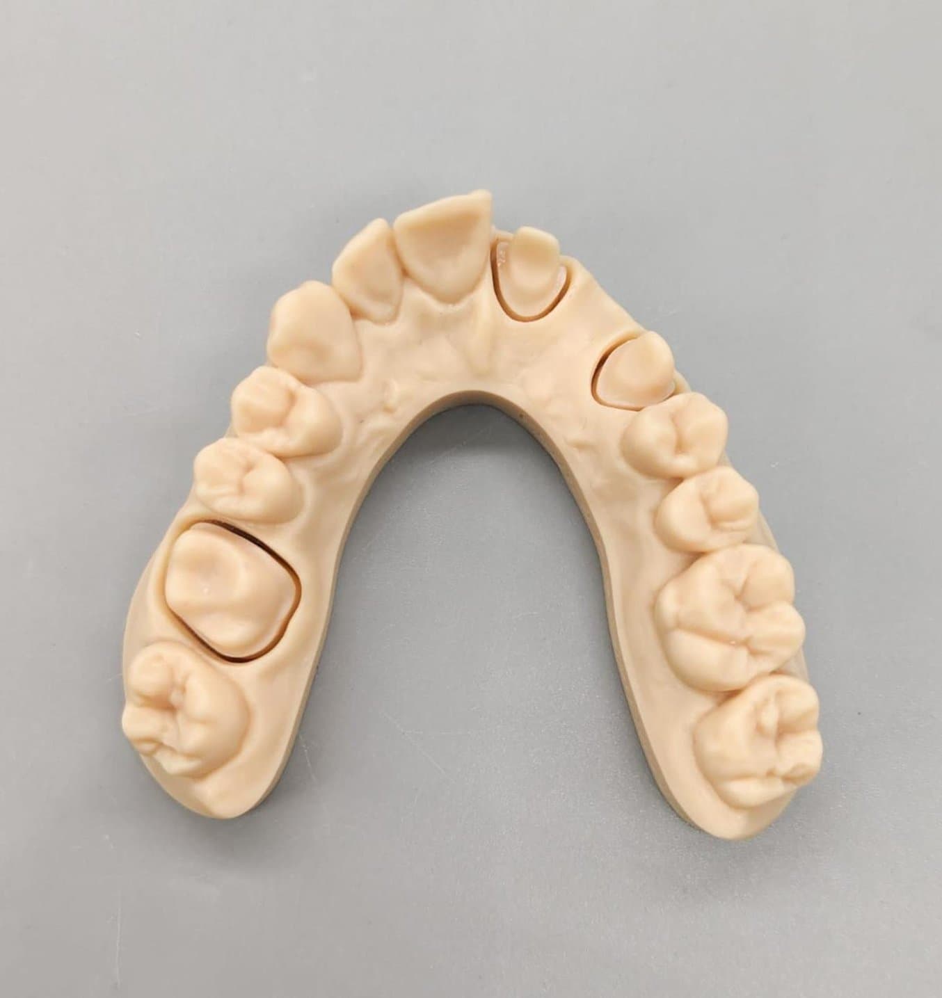
Congratulations, you made a beautiful and accurate restorative dental model!
4. Additional Resources on Designing Dental Models
3Shape
Please consult the 3Shape Dental System documentation that was installed with Dental System, or watch the video tutorial.
Adding drain holes in 3Shape:
For removable dies, 3Shape automatically adds fit check holes to the die slot. These holes also act as drain holes for the die slot.
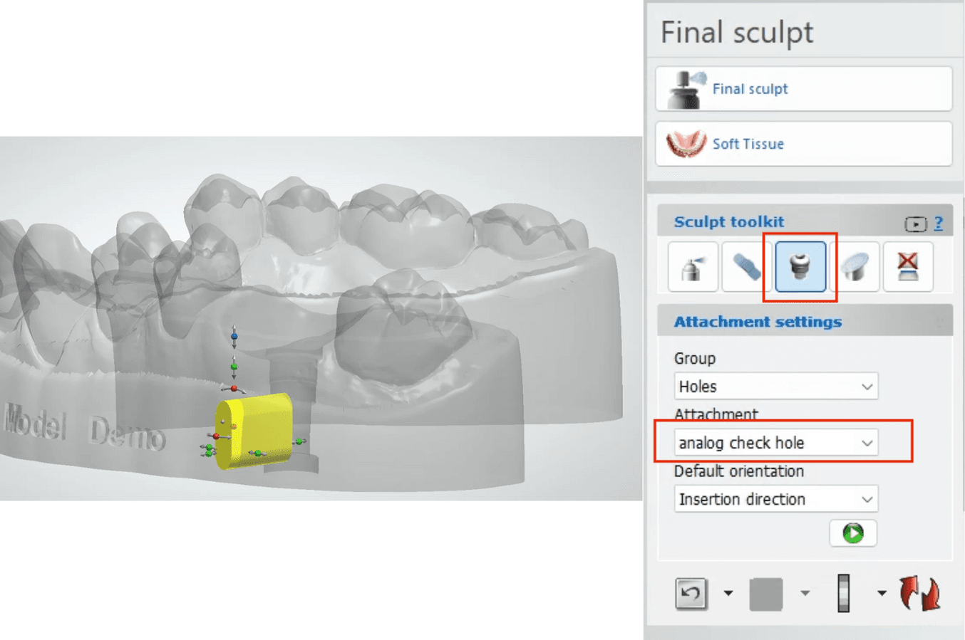
For implant analogs, Formlabs provides an attachment library that installs with the Precision Model Resin DME.
-
Select the “analog check hole” attachment.
-
Place the hole in the model. Placement of the hole should be at a location that allows visualization of the seating of the analog without affecting the security of the analog position.
exocad
Please consult the exocad model creator Wiki here, or watch the video tutorial.
Adding drain holes in exocad:
For drain holes, exocad requires users to manually add to the model. The software comes with a model attachment designed for this purpose.
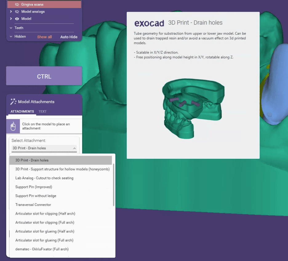
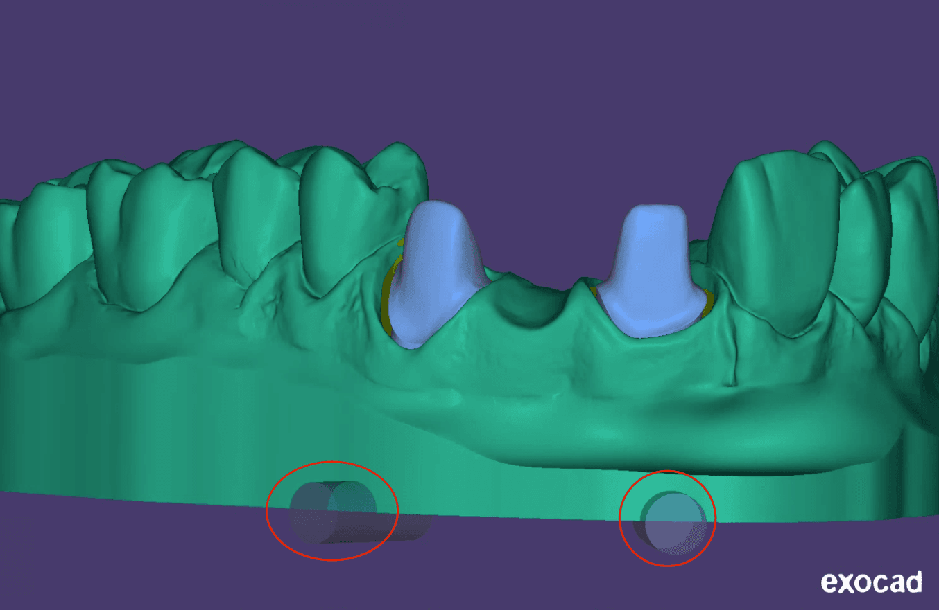
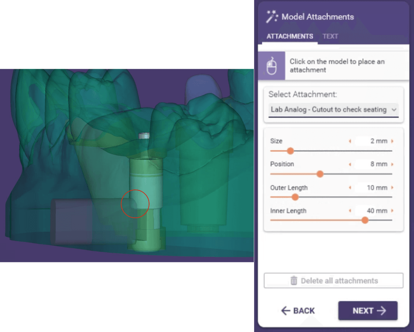
For implant analog drain holes, exocad provides a library for this purpose, which can be found during the attachment step in Model Creator:
-
Select the “Lab Analog - Cutout to check seating” attachment.
-
Place the hole in the model. Placement of the hole should be at a location that allows visualization of the seating of the analog without affecting the security of the analog position.
Additional Resources
Explore Formlabs dental resources for in-depth guides. step-by-step tutorials, white papers, webinars, and more.


