Caution
Always use nitrile gloves when handling uncured resin.
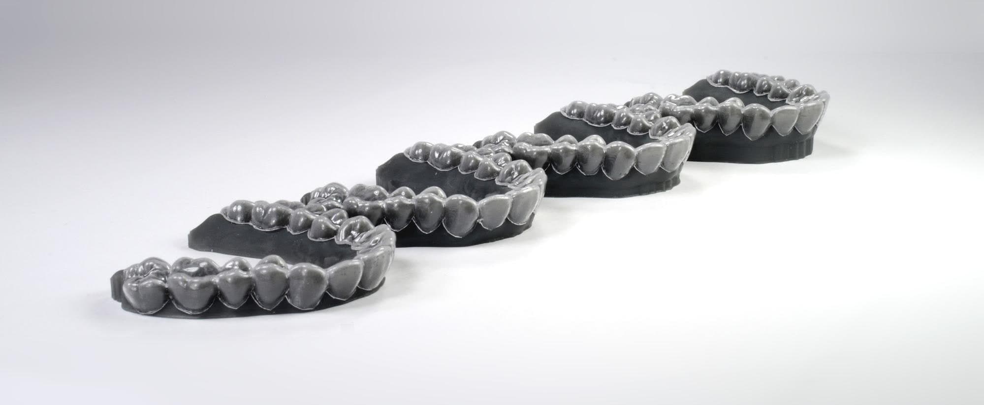
Producing thermoformed clear aligners and retainers enables practices and labs to provide a valuable service to patients and clients while saving time and costs. This application guide details the clear aligner and retainer workflow using a Formlabs 3D printer, from start to finish.
Producing thermoformed clear aligners and retainers enables practices and labs to provide a valuable service to patients and clients while saving time and costs. This application guide details the clear aligner and retainer workflow using a Formlabs 3D printer, from start to finish.
Essentials
Needed From the Orthodontist or Dentist
Required Hardware, Materials, and Software
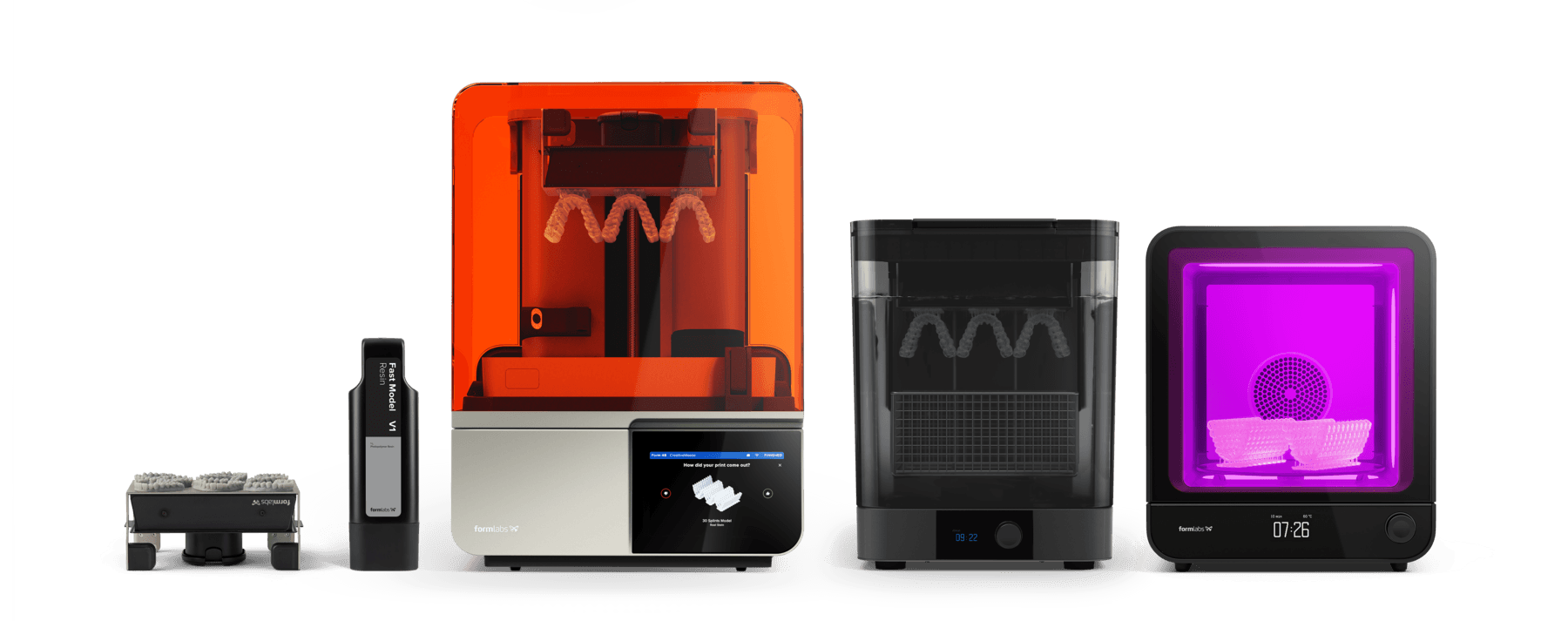
Made by Formlabs:
Formlabs SLA 3D printer with a compatible Resin Tank and Build Platform
PreForm Dental Software (free)
Made by Third Parties:
Dedicated aligner CAD software
Thermoforming machine
Thermoforming sheets
Handpiece
Cutting and finishing tools
1. Scan
To create the necessary models, a digital impression compatible with your CAD software is required. This data can be obtained by either scanning the patient directly with a 3D intraoral scanner, or by scanning a physical impression or plaster model using a desktop 3D scanner.

2. Design
There are many aligner planning software options available. Ensure your chosen CAD software supports STL or OBJ file export for compatibility with Formlabs PreForm software. Clear aligner treatments require multiple model sets and specialized orthodontic CAD software.
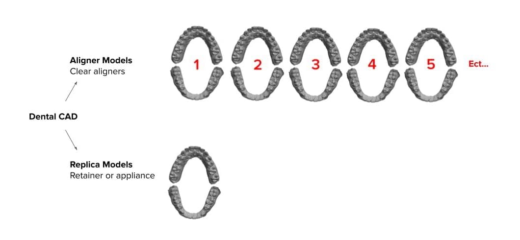
Aligner models versus retainer models. A retainer model does not need any design or steps and can be created in PreForm Dental using Scan to Model.
Treatment planning and setup are done inside the software from the digital impression and sometimes CBCT data. Once complete, each substep is generated into the various stages of the treatment as individual 3D printable (STL) model files. Clear retainers only require a simple replica or diagnostic model file.
2.1 Design Recommendations
Hollow Models
Note
Formlabs recommends printing solid models to reduce post-processing difficulty and breakage.
Some dental CAD software produces hollow models. When designed correctly, hollow models can decrease print time and reduce unit cost. If hollowing a part, ensure that the wall thickness is at least 3 mm.
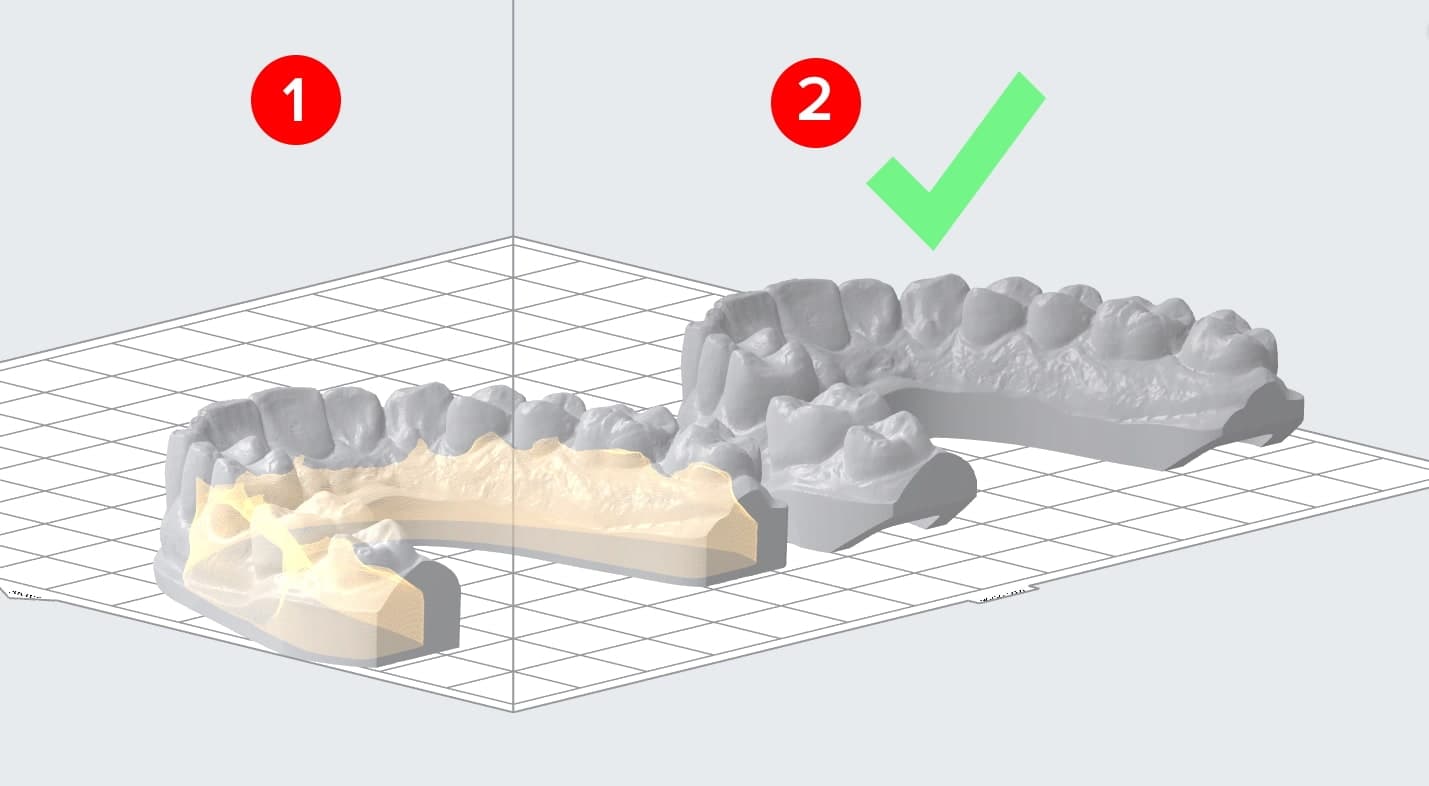
Cupping and Hollow Models
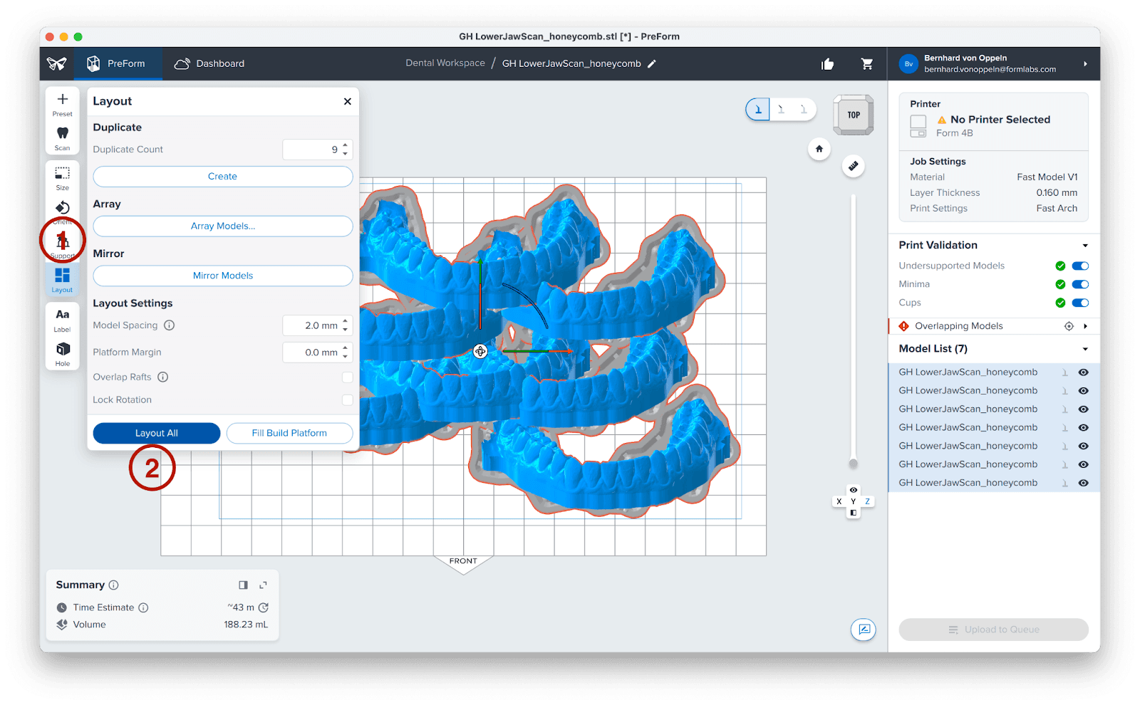
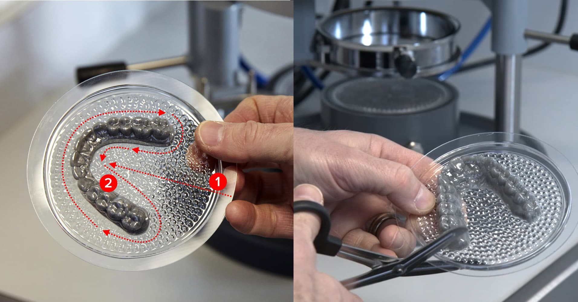
For optimal speed, resin consumption, and accuracy, we recommend printing models directly on the build plate. When printing hollow models flat on the build plate, it's crucial to add ventilation holes to prevent resin from being trapped, which can create a suction cup effect. PreForm will identify and highlight these cupping issues in yellow (1). Ensure the model is open to the outside (2).
Model Height
To facilitate easier removal of thermoformed appliances, design models with a height of 15-20 mm. If your software does not allow control of the model height, you can control the effective height of the thermoformed surface by using pellets during thermoforming. This approach addresses the issue of thermoforming material stretching too far around overly tall models, which can make appliances thinner than expected and removal difficult.
2.2 Optional: Prepare and Print With Formlabs Scan to Model
For a simple retainer model, specialized CAD software isn't necessary. PreForm Dental's Scan to Model feature allows you to create a model directly from a raw intraoral scan. This feature supports STL or OBJ formats, which are commonly used by most modern intraoral scanners. Click on the image below to see how.
3. Job Set-up
Note
If you are new to PreForm software, please refer to this playlist on our YouTube channel.
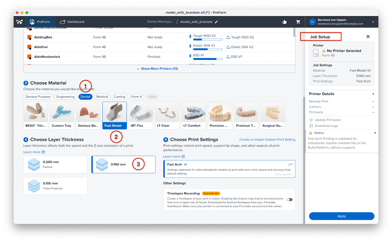
Filter the material options by clicking on Dental in the material selection options (1). We recommend using Fast Model Resin (2) for thermoforming models. You can choose the desired layer height for printing. Taller layers result in faster print time. 0.160 mm is a good balance between speed and detail and was developed for this type of model (3). Fast Model Resin also offers 0.1 mm and 0.2 mm layer height. 0.1 mm gives you the best detail rendering, and 0.2 mm is our fastest setting.
3.1 Import File(s)
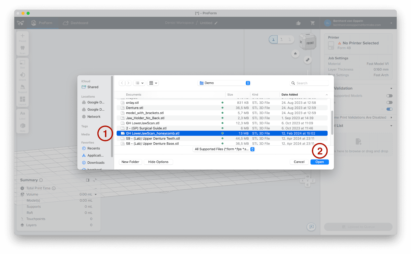
Use the File menu to locate your model(s) (1), then click Open (2). Alternatively, you can drag and drop files into PreForm.
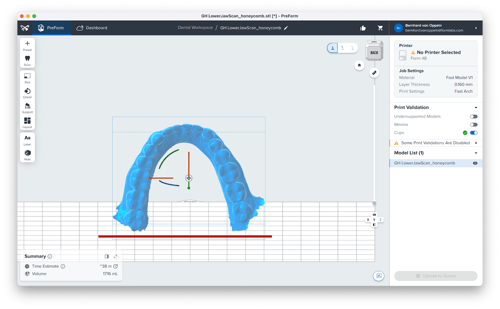
3.2 Orientation
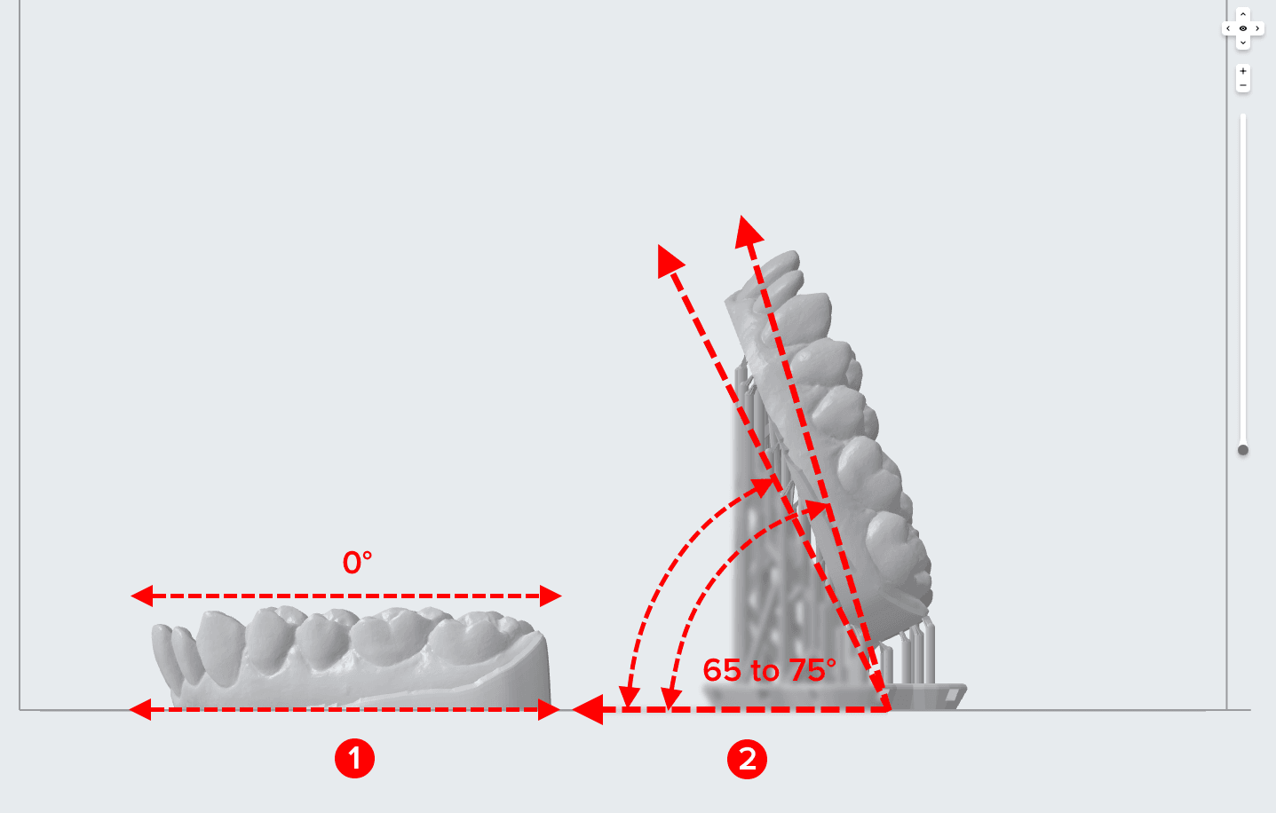
The two ways we recommend printing orthodontic models:
Directly on the build platform (1), for the highest accuracy, speed, and lowest resin consumption.
Near vertical (2), for the most parts per print.
When printing vertically, we recommend a model angle between 65 and 75 degrees.
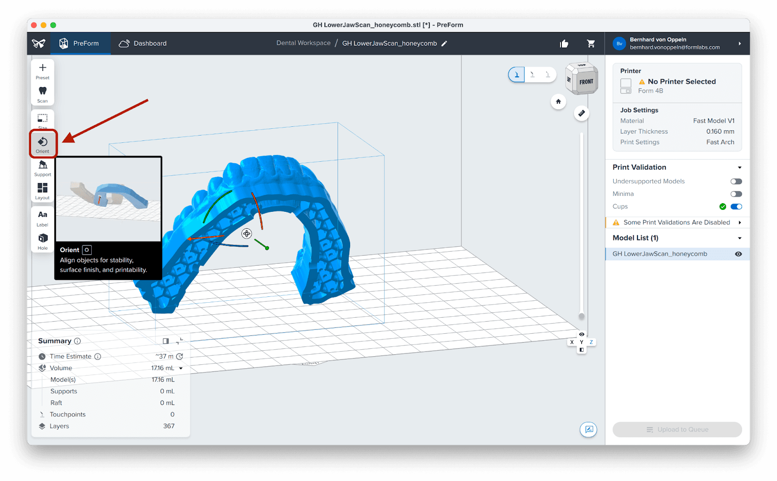
To put your model flat on the build plate, click on the Orient icon.
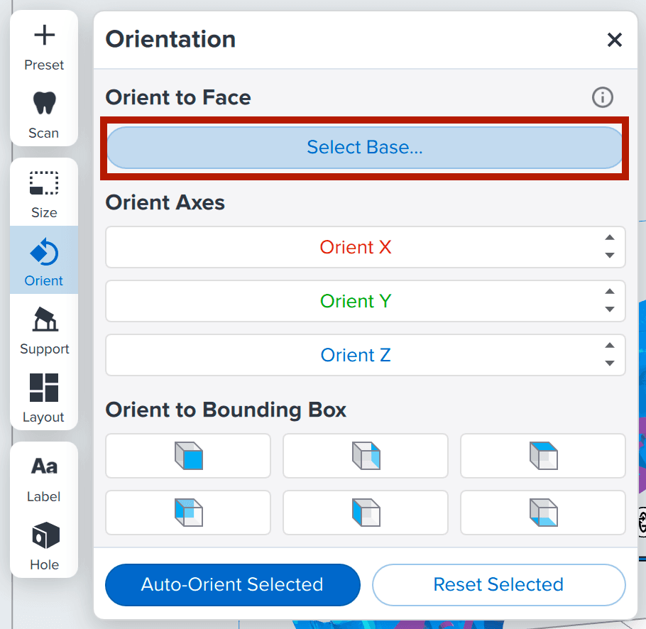
Then click Select Base.
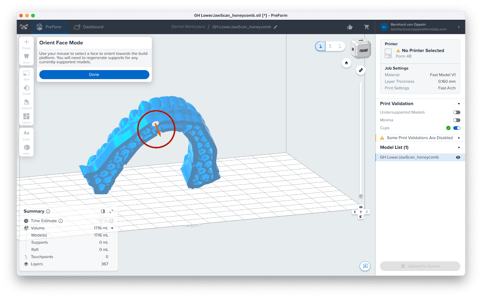
Finally, move the mouse cursor to a flat area of the model’s bottom. An orange arrow will help you preview the face orientation at the cursor position. Click here, and this face of the model will snap to the build plate Your model is now perfectly positioned for printing without supports.

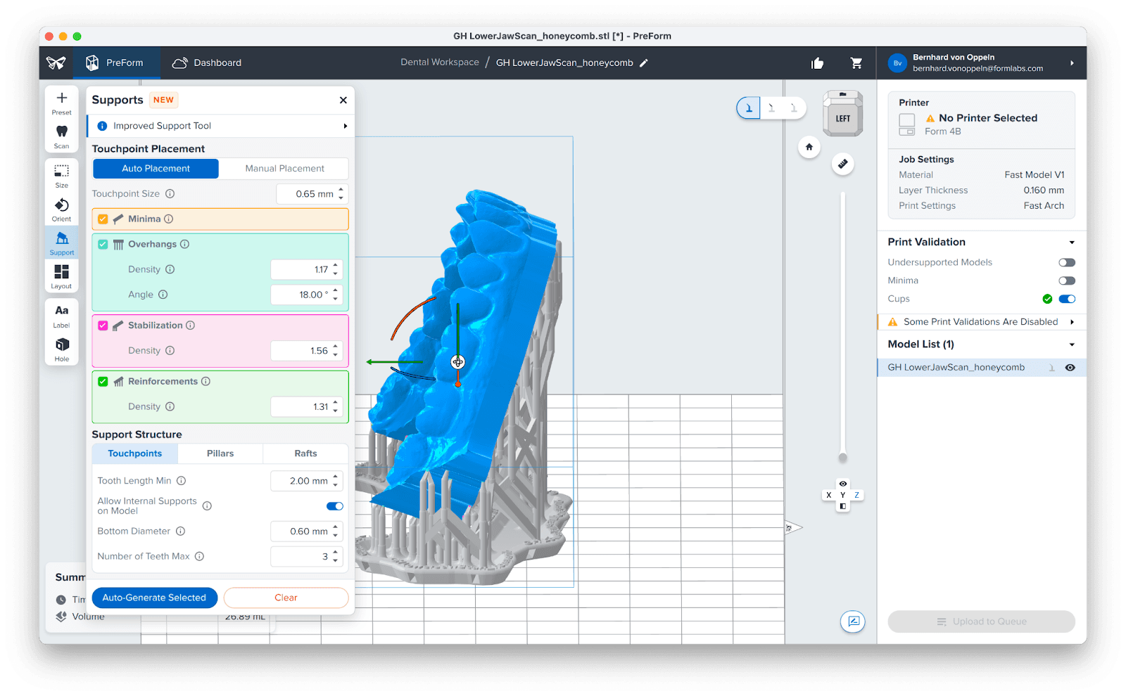
3.3 Vertical Models and Support Structures
When setting up your models for vertical printing, rotate and drag the models so that the rear-most molars are in similar alignments. This can be easily accomplished by using the rotation manipulators of your selected model in PreForm. Please check out the playlist on our YouTube channel to learn more about how easy it is to use PreForm Dental.
For dental arches with open ends, orient them so that the free ends are parallel to the build plate. This is considered best practice.
Next, navigate to Support and select Auto-Generate Selected. For multiple models, you can select them all and process them simultaneously.
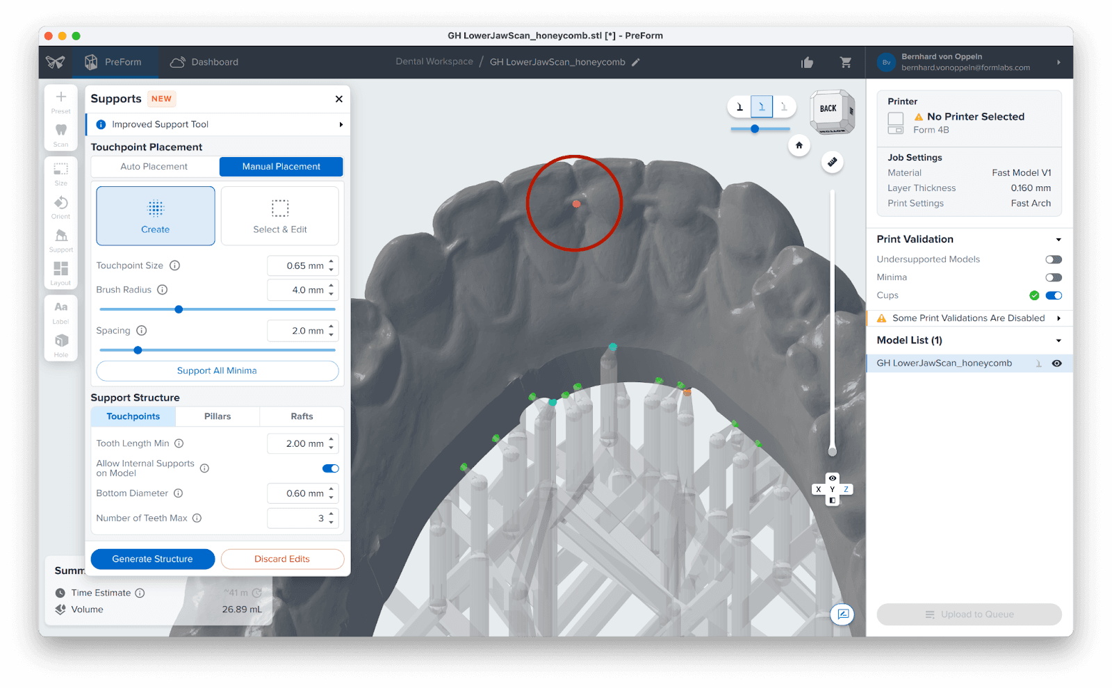
3.4 Manual Support Editing
It is good practice to check for misplaced supports, like a support on a tooth surface. If a support touchpoint is not in an ideal location, you can edit its position. You can access this option by clicking Manual Placement in the Supports menu.
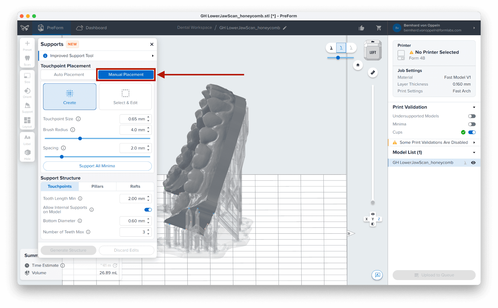
Locate any unwanted supports that might affect the fit of your aligner, and use the mouse to remove them.
Note
PreForm's Auto-Generate Selected function automatically calculates supports for your chosen resin, ensuring accurate prints. Manually adjusting these supports may negatively impact printability, so exercise caution.
3.5 Printing Layout
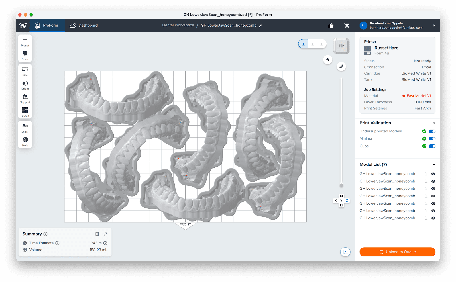
Whether you are printing on support structures or directly on the build platform, position the parts so they do not overlap each other. Overlapping parts will be outlined in red. When trying to lay out a print job with many models, PreForm has a powerful built-in function to automate this process.
3.6 Transfer the Job to the Printer
Click on the button that says Send to Printer, or Upload to Queue, depending on your printer status.
3.7 Start Print
Shake the resin cartridge and then insert the cartridge, a build platform, and a compatible resin tank into the Formlabs 3D printer.
Begin printing by selecting the print job from the printer’s touchscreen.
Follow any prompts or dialogs shown on the printer screen.
The printer will automatically complete the print.
4. Post-Processing
4.1 Part Removal
Caution
Always use nitrile gloves when handling uncured resin.
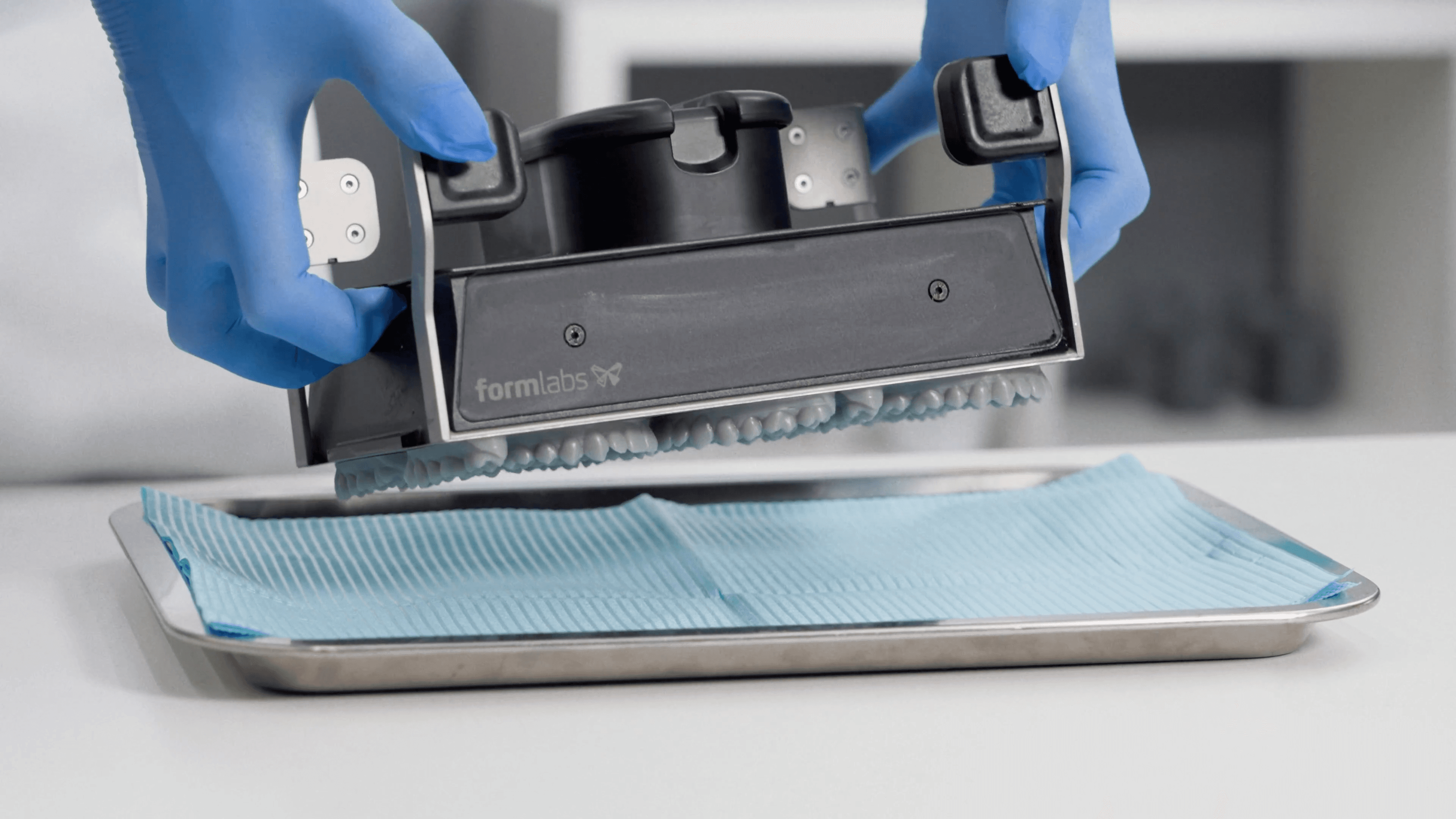
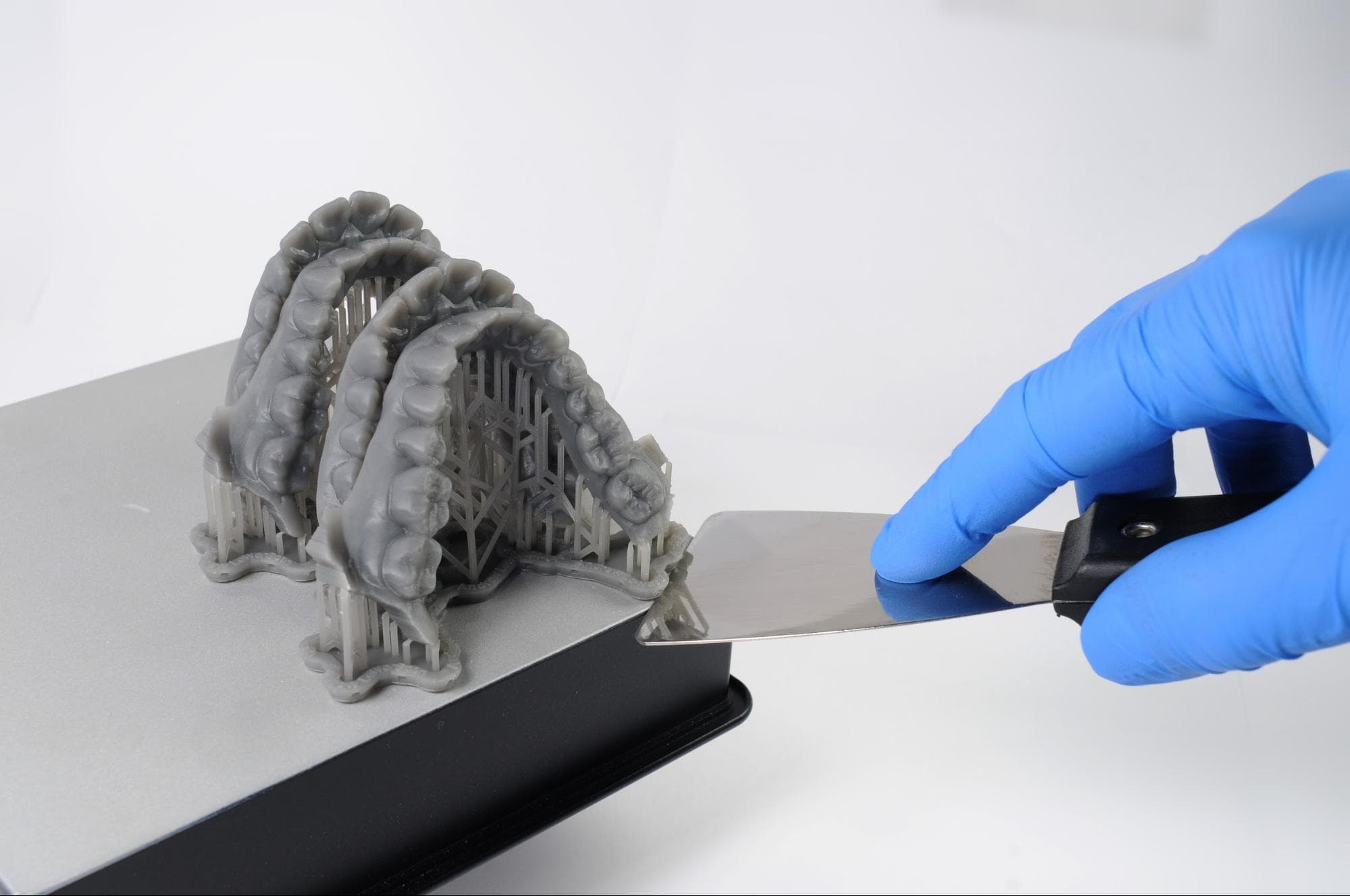
Part removal is straightforward with a Flex Build Platform or Build Platform 2: simply push the handles to release the models. For standard build platforms, use either a spatula (3) or the part removal tool (1) from the Finish Kit. This applies to all parts, regardless of whether they are printed flat or with supports. Parts printed with supports will have a raft that includes a chamfer, which facilitates tool access underneath the part.
To avoid damaging your parts, make sure that:
The tool gets completely under the model.
You do not put too much force on one area of the model, work around the perimeter.
4.2 Wash
Caution
When washing the printed part with solvent, ensure a properly ventilated environment and use protective masks and gloves. Expired or unused resin shall be disposed of in accordance with local regulations.
Place the model in a Form Wash filled with isopropyl alcohol. For more information on the proper washing times and required alcohol purity, please consult this article: Formlabs Resins Washing Times.
For non-biocompatible prints like thermoforming models, you can use Formlabs Resin Washing Solution instead of IPA.
Make sure all parts are fully submerged when washing.
Exceeding wash duration may affect the dimensional accuracy and performance of printed parts.
Using the Standard Finish Kit
For best results in resin removal and surface finish, Formlabs recommends using a Form Wash. Alternatively, if using the Finish Kit, follow these instructions: rinse parts in two buckets with IPA or Formlabs Washing Solution.
4.3 Dry and Inspect
After removing parts from the IPA, allow them to air dry at room temperature in a well-ventilated area for approximately 30 minutes. The drying process can be expedited by using compressed air. Ensure all alcohol has completely evaporated before proceeding.

After printing and washing, thoroughly inspect parts to ensure they are clean and dry. No residual alcohol, excess liquid resin, or residue particles should remain on the surface before proceeding. If wet, uncured resin is still present after drying, submerge the part in clean IPA for approximately one minute, or use a squeeze bottle. Then re-dry the parts as previously described.
4.4 Post-Cure
After washing and drying, place the models into the Form Cure. Select the appropriate preset on the Form Cure for the correct curing time and temperature, and start the curing process.
4.5 Support Removal (optional)
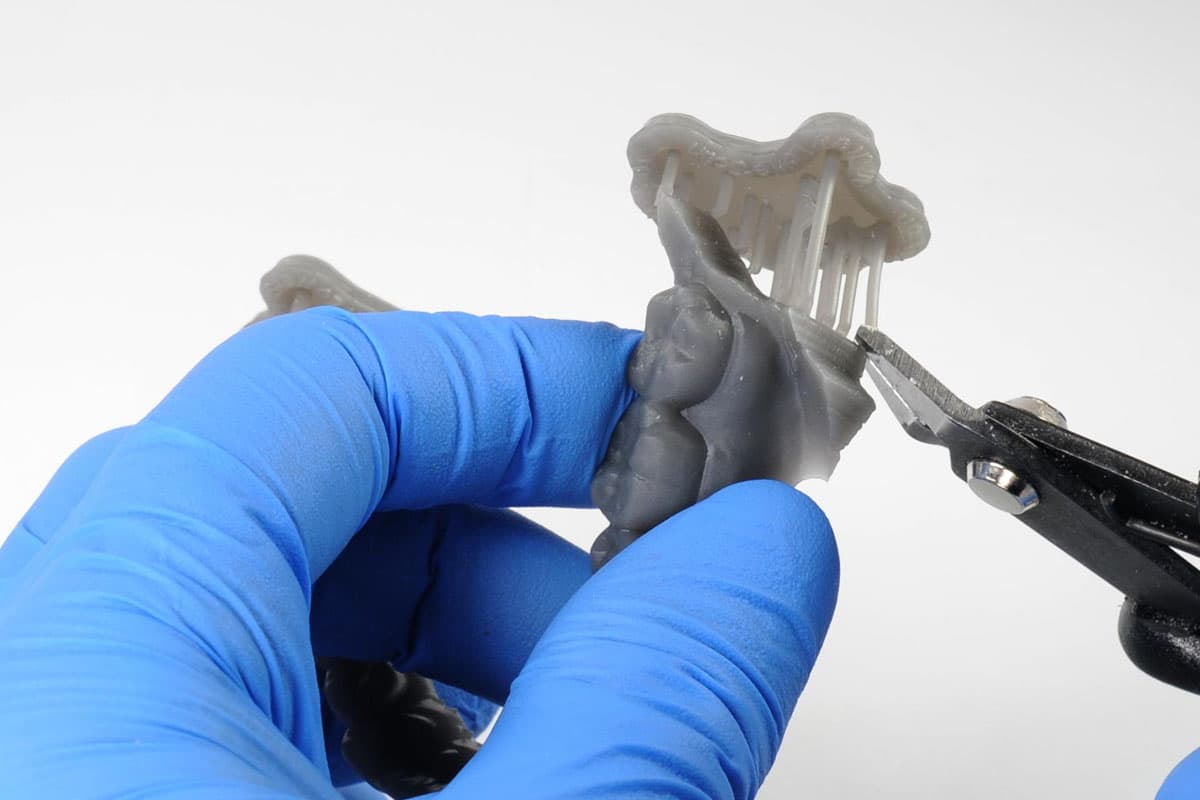
Formlabs SLA printers produce parts with support structures that have minimal touchpoints, enabling easy removal by simply detaching them.
Though ripping supports from a part may be quicker, it can damage the model or leave divots. Therefore, we recommend individually cutting supports connected to critical anatomy.
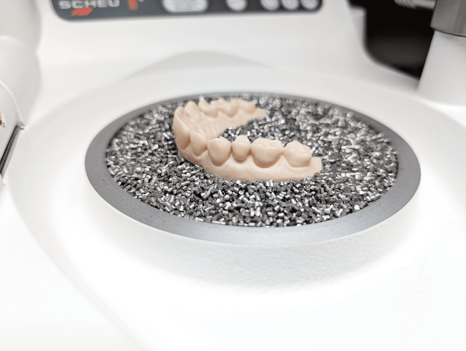
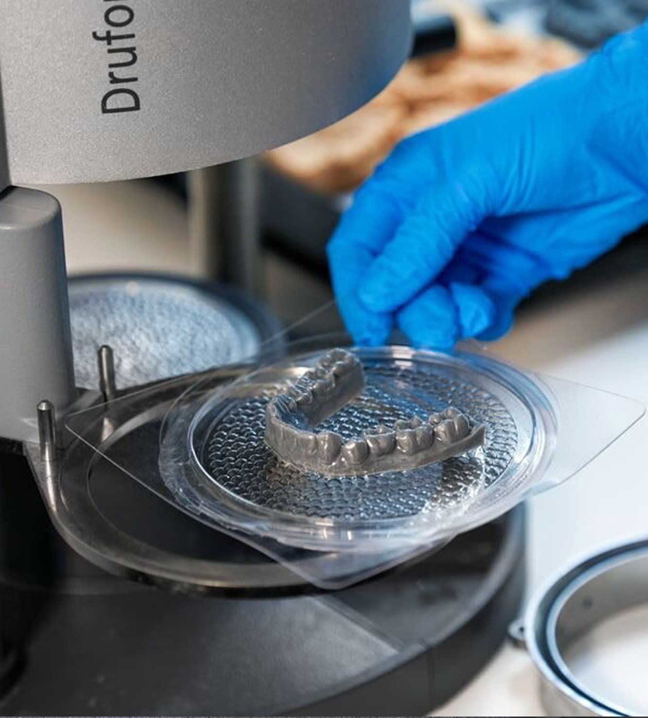
5. Thermoform
To create the appliance, place the model in a dental thermoforming machine. Begin by using the recommended settings for your equipment and sheet material.
5.1 Vacuum vs. Pressure Formers
During the thermoforming process, a plastic sheet is heated to a pliable temperature, typically around 220 °C. It is then either vacuum-sealed or pressure-pressed onto a model. Dental thermoforming machines operate in two modes: vacuum forming or pressure forming. Both methods are effective, but pressure-operated machines offer greater power and reliability. These machines do require access to clean compressed air.
Note
Avoid using thermoforming sheets thicker than 1.5 mm due to the high operating temperature required. Thicker sheets require more time to cool on the model, which could lead to model damage or deformation.
5.2 Thermoforming Best Practices
5.2.1 Preventing Adhesion
Models that are not completely washed and post-cured can adhere to the thermoforming material.
Resin that hasn't been washed will appear shiny and feel tacky. If you notice any shiny areas, wash the part again for one minute.
5.2.2 Model Height for Thermoforming
Depending on the heating cycle, thickness, and brand of the material, results may vary.
Taller models produce thinner appliances (1).
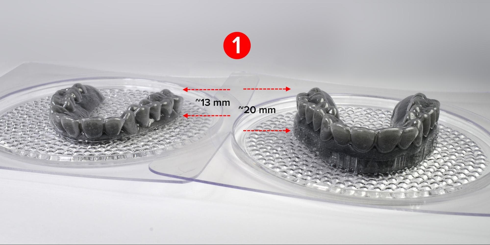
We found pressure-forming materials of 1 mm thickness resulted in an appliance of ~0.7 mm thickness (2).
To maintain consistent thermoforming, you can either use controlled CAD outputs (model height and block-out) or employ pellets or beads to achieve equal heights during the process. See the section on Model Height.
6. Cutting and Finishing
Depending on the thickness of the material used and the preferred method, a variety of techniques can be used for cutting out and finishing the appliance. Experiment and find what works best for you and whoever else is doing the work.
The goals are to be quick, and to produce appliances with clean edges that meet your expectations.
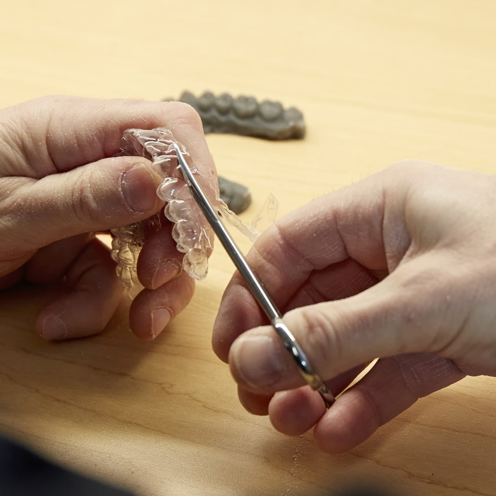
6.1 Cutout
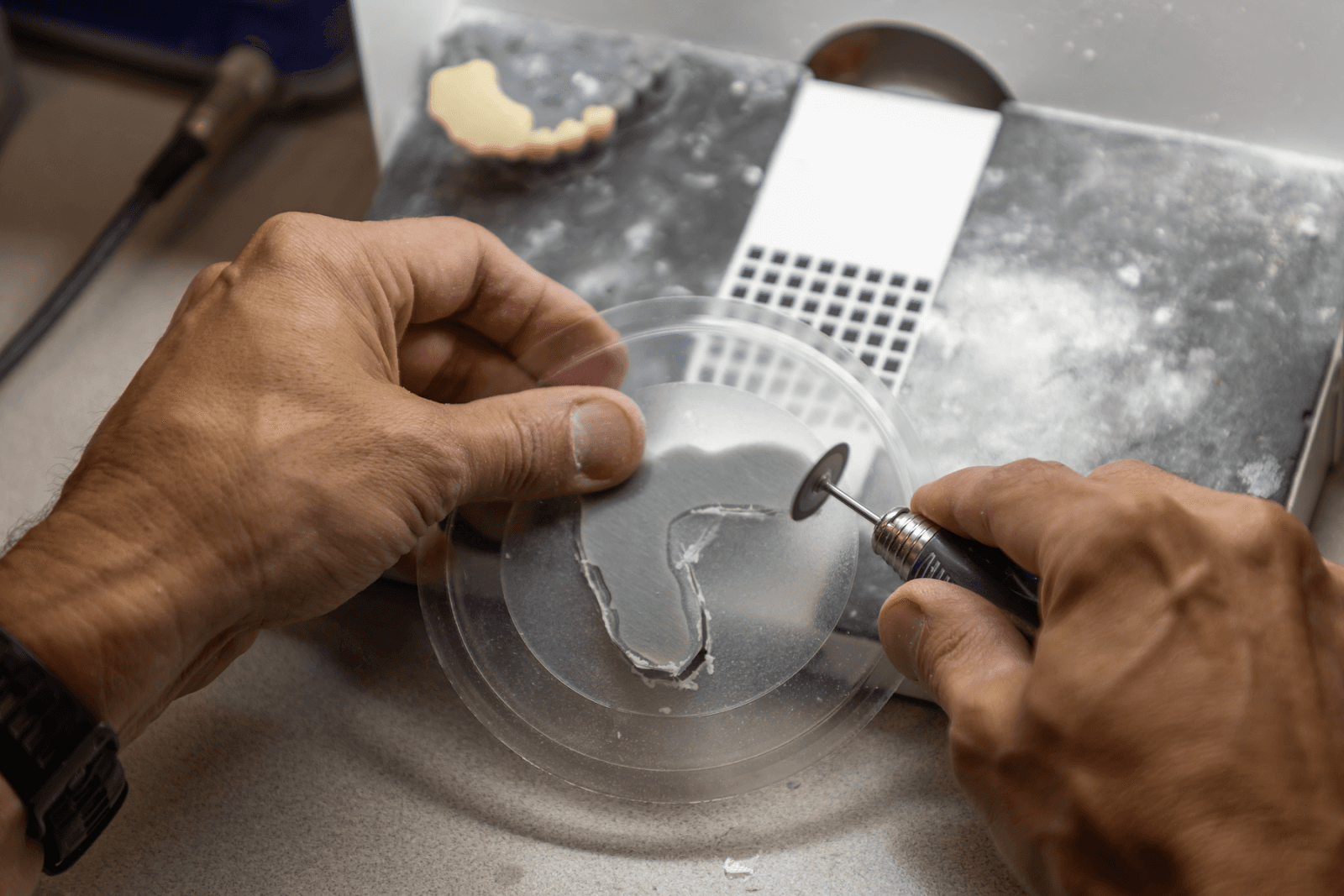
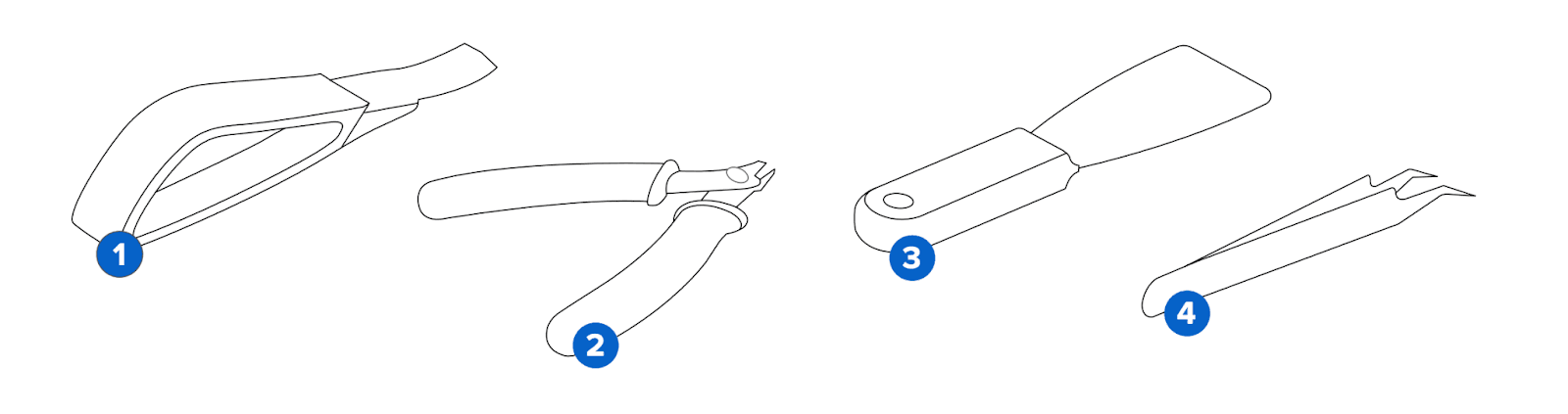
To finalize the appliance's shape, you can either cut its outline directly on the model or trim excess material near the intended outline before removing the sheet from the model. Cutting discs, carbide triangular cutters (see below), or robust scissors are suitable tools.
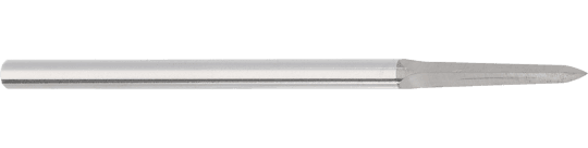
For reference, a triangular cutter is ideal for cutting thermoplastic sheets without heat.
Note
When using rotary instruments, be mindful of the thermoplastic material; regulate pressure and rotation speed to avoid excessive heat accumulation.
6.2 Trimming
Trim the final outline of your appliance. Use rotary tools or specialized scissors. We recommend using specialized sheet scissors for efficiency and to reduce the amount of clean-up needed on cutting borders. These scissors feature micro-serrations for control and to prevent slipping.
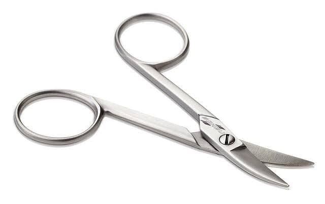
An example of a sheet scissor with micro-serration.
6.3 Automated CNC or Laser Cutting
Depending on the desired outcome and case complexity, the number of aligner steps per patient can be substantial. The manual finishing of these appliances, as previously described, is labor-intensive, driving up time and cost. In response, the dental industry has introduced highly automated cutout workflows, utilizing CNC mills and laser cutters. If you are aiming for high throughput where time and labor costs are a concern, investing in these specialized machines could be beneficial.
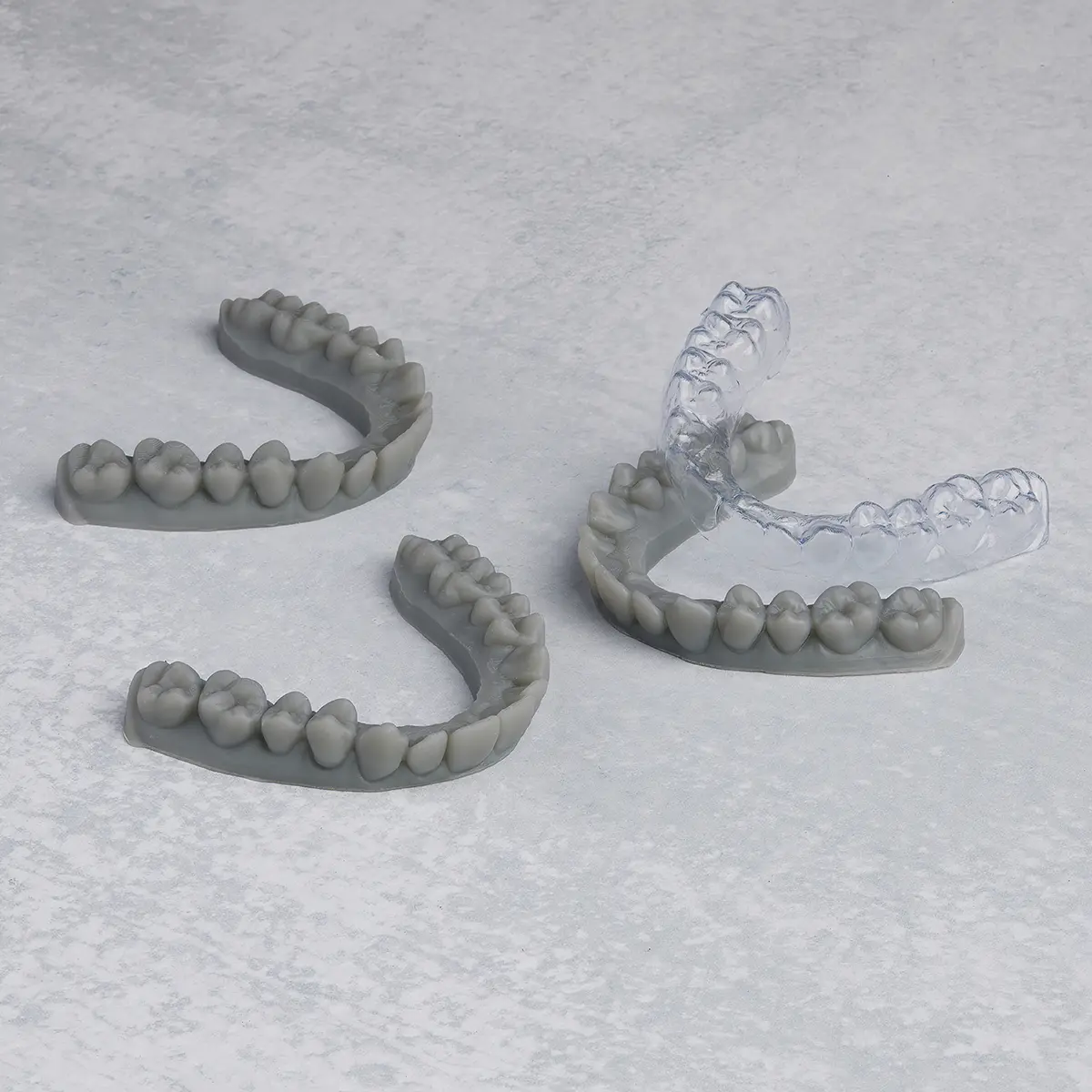
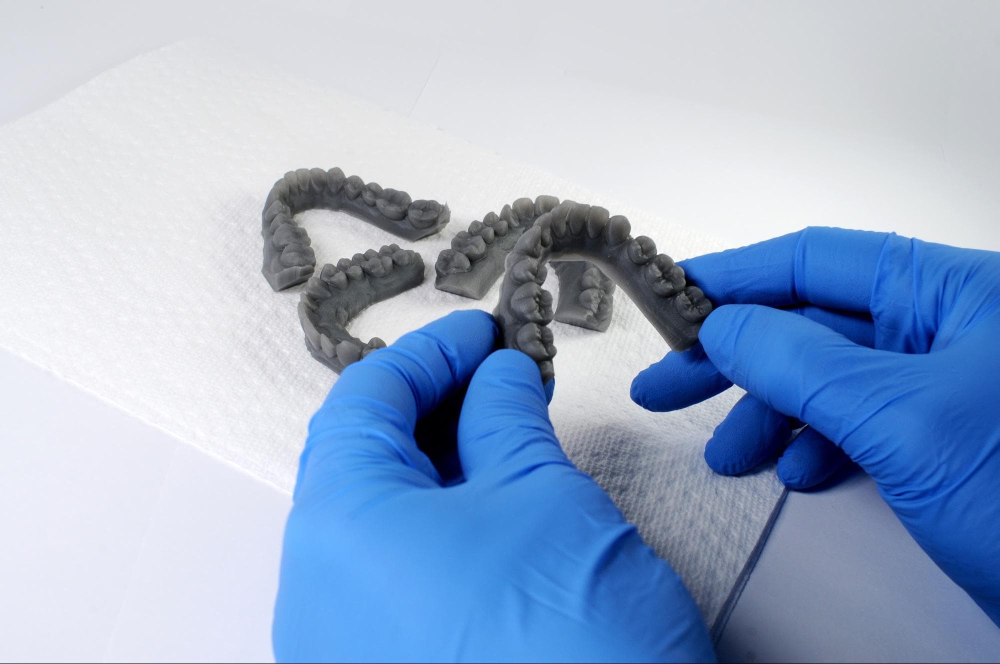
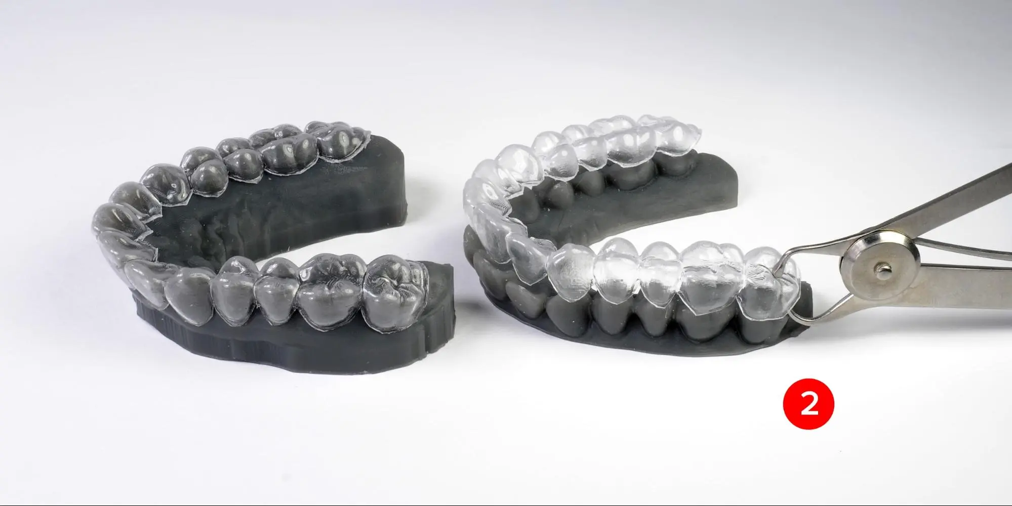
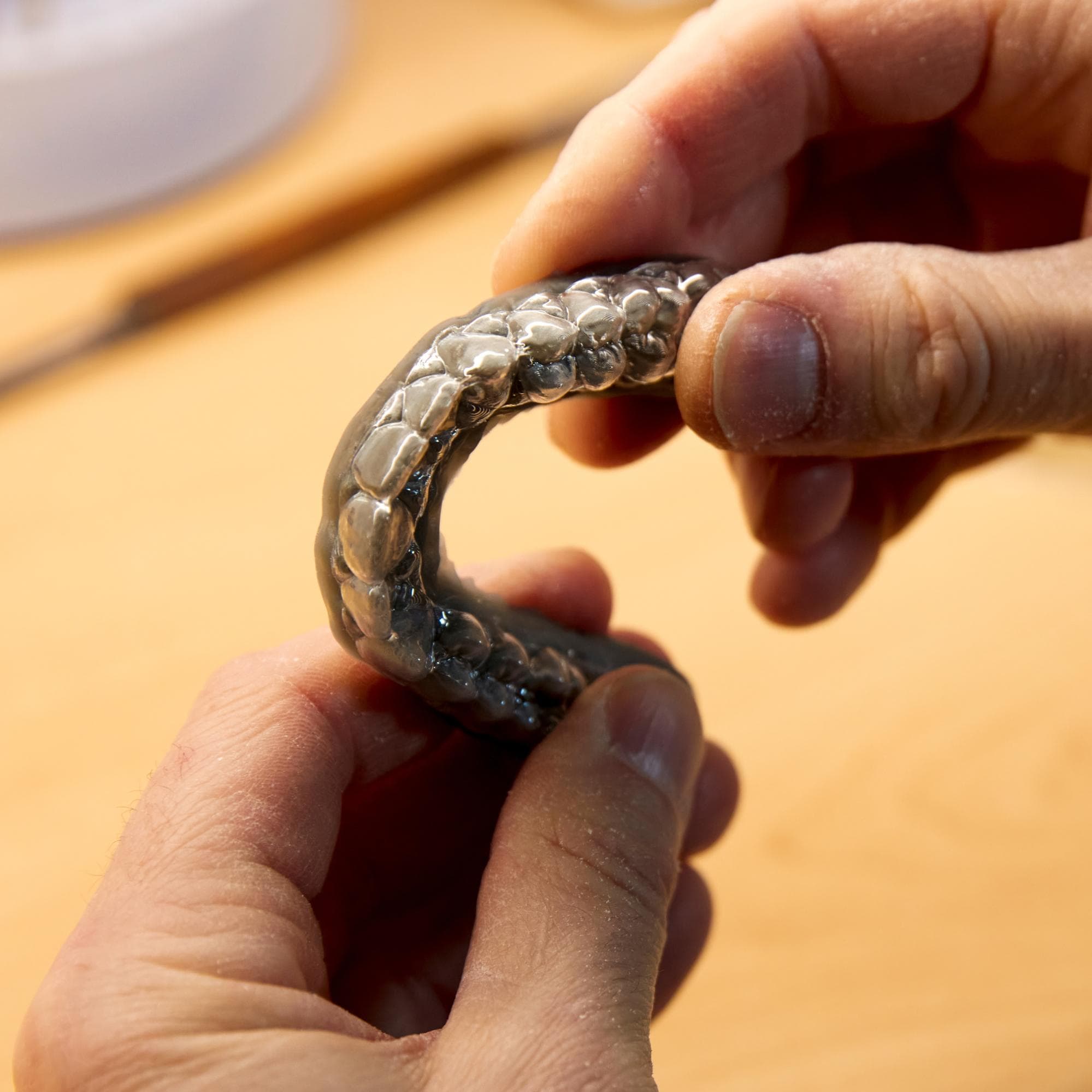
6.4 Finishing and Quality Control
Conduct a quality control and fit check on the model. Ensure the model fits tightly on the dentition and check for any deformations caused by heat during the cutout process.
The appliance should be disinfected and safely packaged for delivery.
7. Disposal
1. Any cured resin is non-hazardous and may be disposed of as regular waste.
2. Liquid resin should be disposed of in accordance with government regulations (community, regional, and national). Dispose of as an unused product.
8. Formlabs 3D Printer and Resin Compatibility
3D printed models for thermoforming clear appliances can be printed using the following Formlabs SLA printers and materials.
|
Printer |
Resin |
|
Form 4B Form 4BL |
|
|
Form 3BL |
Supporting Documents
Additional Resources
Explore Formlabs dental resources for in-depth guides. step-by-step tutorials, white papers, webinars, and more.
Dentistry Made Easier
Form 4B is a blazing fast dental 3D printer that offers the most diverse materials library for dentistry and orthodontics. Create high-quality dental models and biocompatible appliances fast, with easy workflows, leading reliability, and stunning part quality using the Form 4B ecosystem.