Precautions:
-
When washing the printed part with solvent, ensure a properly ventilated environment and use protective masks and gloves.
-
Expired or unused IBT Flex Resin shall be disposed of in accordance with local regulations.
This application guide is a step-by-step walkthrough of the workflow for producing indirect bonding trays for orthodontic bracket placement with Formlabs IBT Flex Resin and Formlabs Dental 3D printers. Always consult the Manufacturing Guide and Instructions for Use for the absolute requirements.
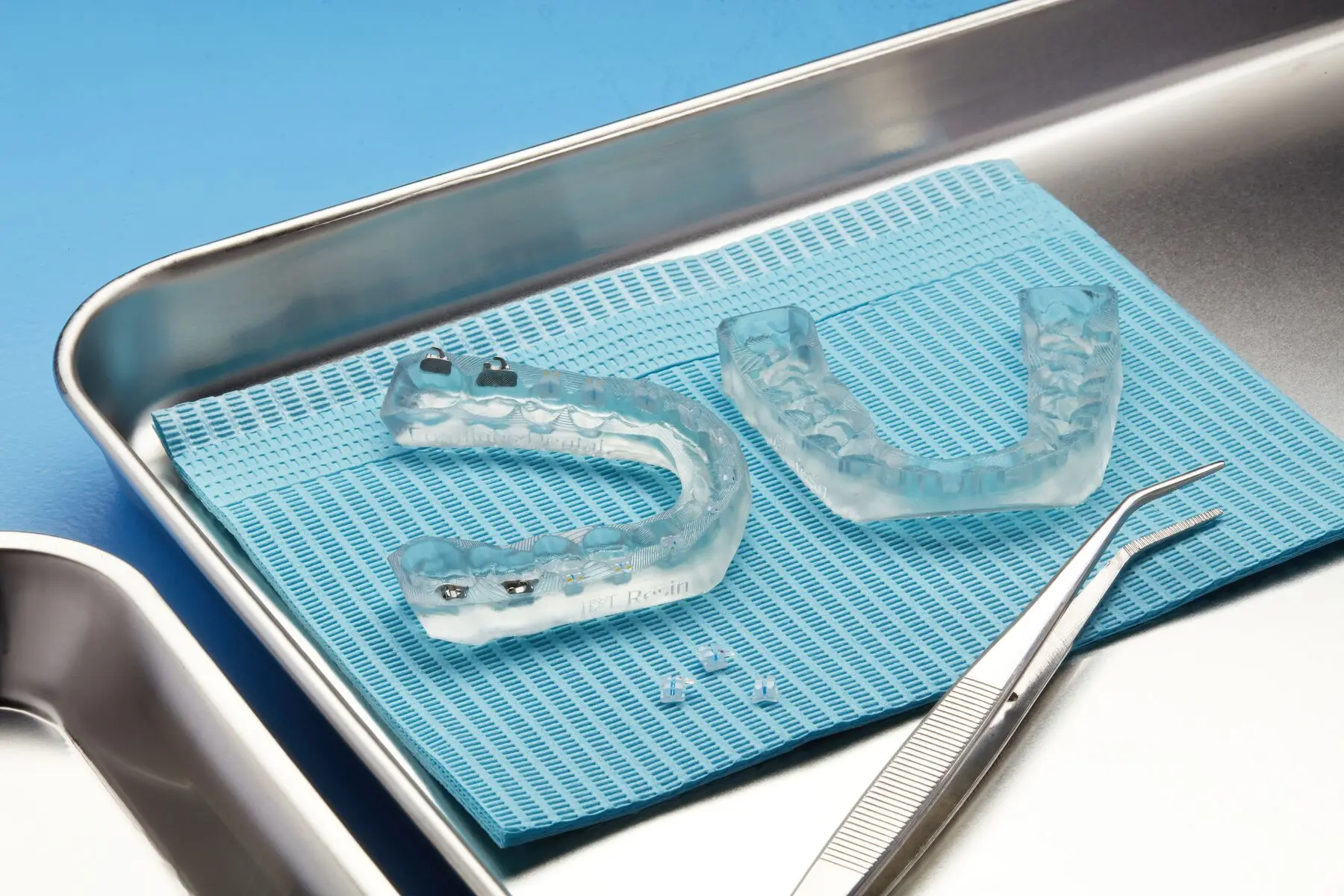
IBT Flex Resin is a flexible biocompatible material for efficient, accurate dental bracket placement. 3D printed indirect bonding trays reduce chair time and increase patient comfort by placing all of the brackets or entire quadrants at once. IBT Flex Resin is a Class I medical device that offers optimized tear strength, translucency, and flexibility, for appliances that are easy to plan, easy to use, and easy to remove.
This application guide is a step-by-step walkthrough of the workflow for producing indirect bonding trays for orthodontic bracket placement with Formlabs IBT Flex Resin and Formlabs Dental 3D printers. Always consult the Manufacturing Guide and Instructions for Use for the absolute requirements.
IBT Flex Resin is a flexible biocompatible material for efficient, accurate dental bracket placement. 3D printed indirect bonding trays reduce chair time and increase patient comfort by placing all of the brackets or entire quadrants at once. IBT Flex Resin is a Class I medical device that offers optimized tear strength, translucency, and flexibility, for appliances that are easy to plan, easy to use, and easy to remove.
1. Essentials
Required Hardware, Software, and Materials
Made by Formlabs:
Formlabs SLA 3D printer with a compatible Resin Tank and Build Platform
PreForm Dental Software (free)
Note:
IBT Flex Resin is not compatible with the Form 2 3D printer.
Made by Third Parties:
Dental design software for the design of the bonding tray or a dental design service provider
Heat-resistant clear container (for curing)
Optional: light-safe container for storing the appliance
Required Clinical Inputs and Data
A physical or digital impression
Patient treatment plan data
A CBCT scan, which is optional depending on the specific design software requirements
2. Preparation
To design an indirect bonding tray, dental software requires a digital impression of the patient's anatomy. This digital data can be acquired through an intraoral scan, a negative scan of a physical impression, or a scan of a plaster model using a desktop 3D scanner.
Although not mandatory, some indirect bonding tray design software can utilize CBCT data. This data is highly beneficial for both case planning and setup.
3. Design
This section provides essential design parameters and best practices for creating an indirect bonding tray. While these guidelines are generally applicable across various software solutions, such as 3Shape Ortho System, BlueSkyPlan, Onyxceph, OrthoSelect, or others, users should consult their specific CAD provider's documentation. Note that the visuals in this section are from 3Shape Ortho System.
Alternatively, you have the option to outsource the appliance design and manufacturing file creation to a dental CAD service provider, such as a specialized dental laboratory or dental design center, by sending them the digital impression and your requirements.
3.1 Construction and Appliance Offset Recommendations and Requirements
3.1.1 Insertion Direction
For optimal bracket retention and ease of insertion, select the correct insertion direction, ideally straight from the occlusal or slightly from the frontal aspect. The insertion direction is critical as it affects how offsets and undercuts are applied.
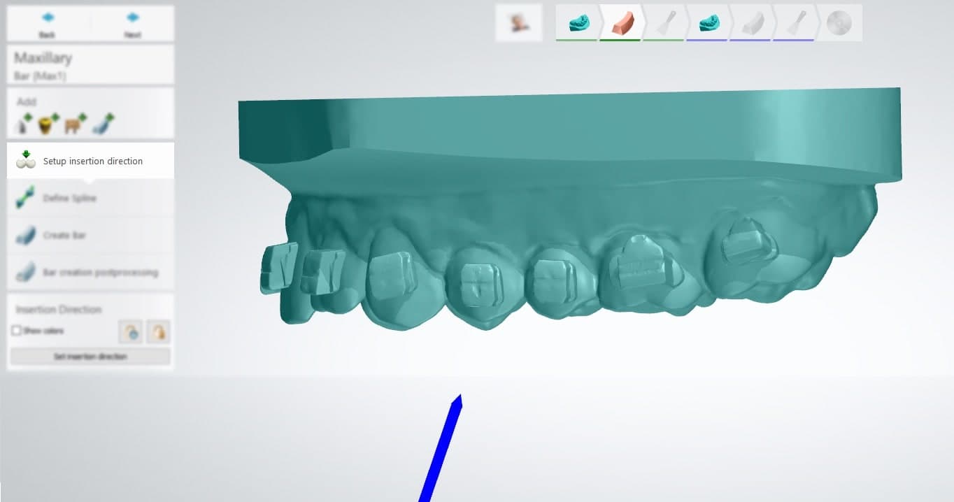
3.1.2 Appliance Construction and Type
There are typically two ways to set up and create indirect bonding trays:
Bar
Offset
For IBT Flex Resin, Formlabs offers compatibility with both bar and offset designs.
The bar design may offer the following advantages during use:
Flexibility around brackets since the appliance is still thin in critical areas
Thicker bottom surface providing some useful rigidity to the appliance
Ability to print directly on the build platform, removing the need for support structures
Note:
This application guide will primarily focus on the bar design, as it is the most frequently utilized.
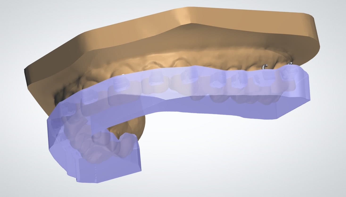
1. Bar design example
Note:
There are different CAD offsets for bar designs and offset designs, see details below.
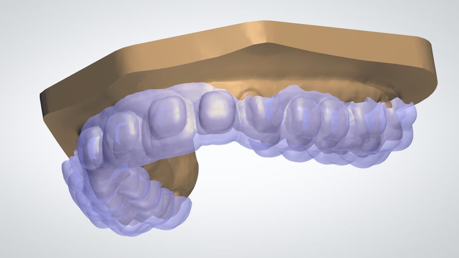
2. Offset design example
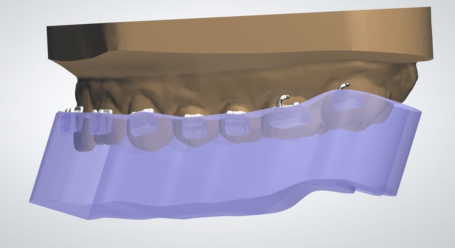
3.1.2.1 Container Design and Coverage
In our testing, we found half- or three-quarter container coverage the best way to design indirect bonding tray appliances, especially using the bar design.
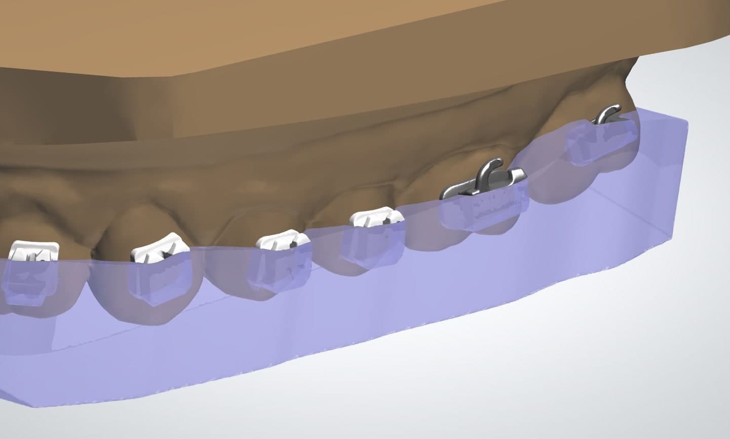
Example of a three-quarter and full container or bracket coverage.
3.2 Bar Design Settings and Offsets
Please respect a minimum wall thickness of 2 mm for the tray.
Note:
The parameters provided are tailored for 3Shape Ortho System. Note that the available options and terminology may vary depending on the specific design software you are using.
3.2.1 Containers ( 3Shape )
|
Parameter |
Recommended Value |
|
Inner Surface Offset |
0 mm |
|
Block Out Angle |
0° |
|
Retention Amount |
0 mm |
|
Prolongation Length |
1 mm |
|
Bracket Slot Block-out |
Yes |
3.2.2 Finalization ( 3Shape )
|
Parameter |
Checkbox |
|
Dot Not Modify |
|
|
Subtracted Model |
x |
|
Use Offset for Inside Surface |
|
|
Remove Undercuts |
|
|
Extra Combine with Model |
|
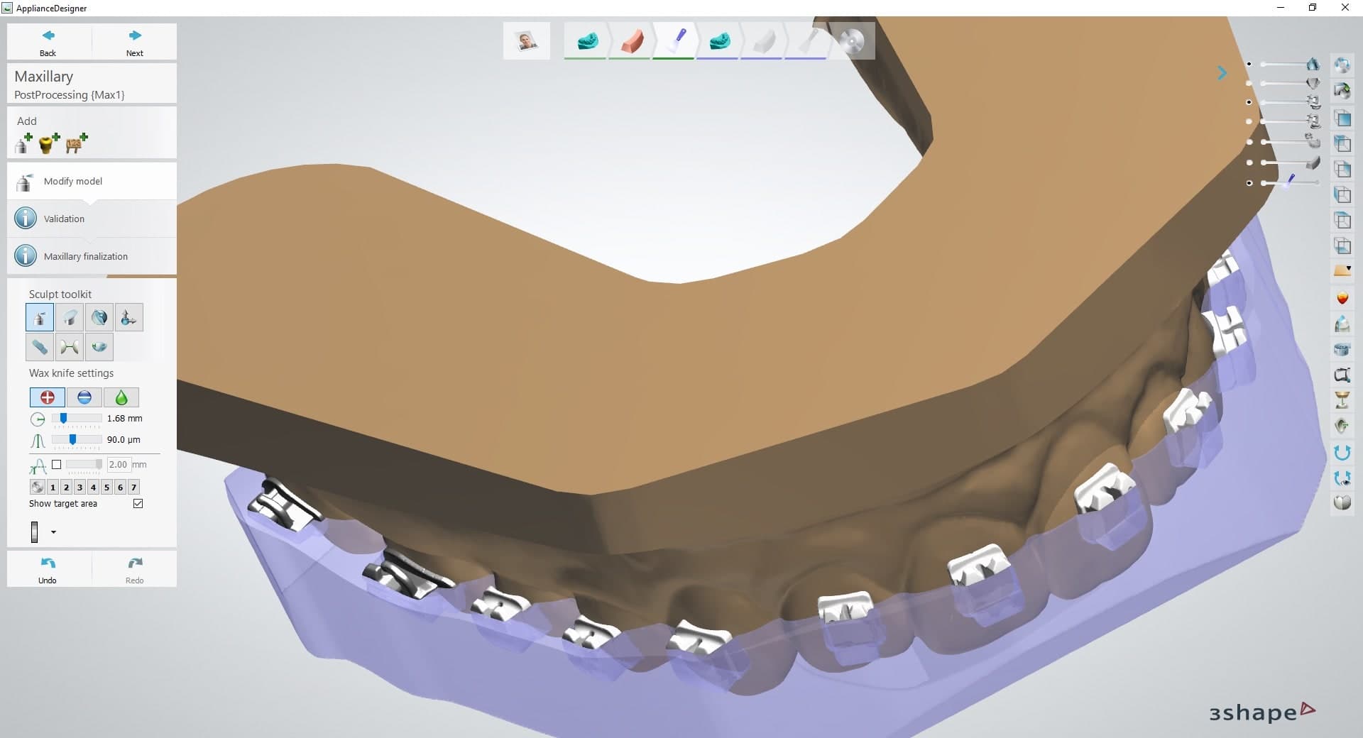
3.2.2.1 Optional: Using Plane Cuts
The bar-type design, if supported by your software, is an excellent choice because it allows for printing flat on the build plate, eliminating the need for supports.
For instance, within the Bar Design workflow of 3Shape Ortho System, this setup can be achieved during the final step, Modify model.
The suggested modifications, illustrated in the two screenshots below, utilize the plane cut tool. The primary objective of the first cut is to flatten the tray's occlusal surface (1). A secondary cut is then applied in this example to introduce a chamfer (2), which is intended to facilitate the removal of the parts from the build plate post-printing.
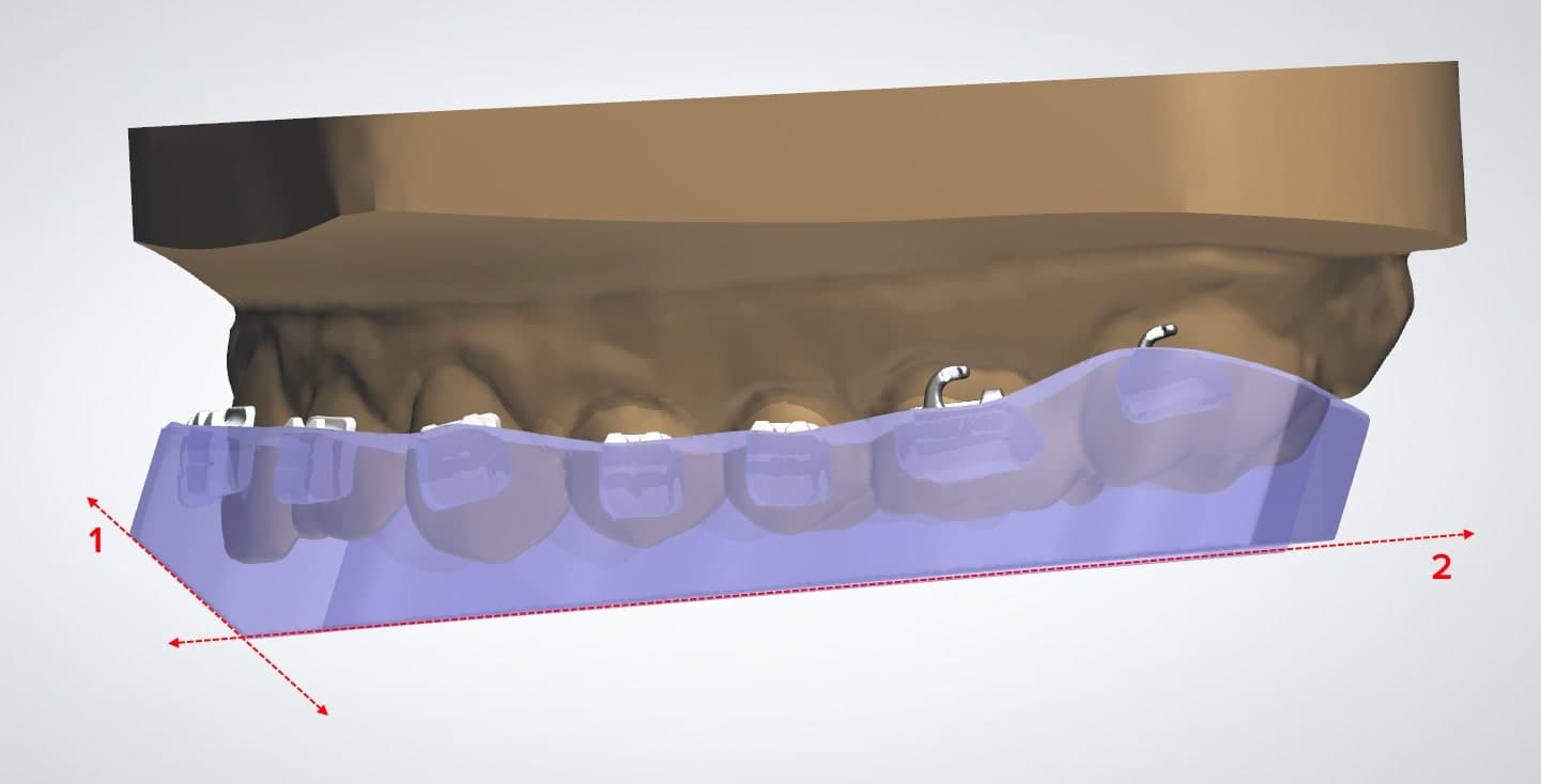
Side-by-side: the raw bar design, and the design after two plane cuts.
Note:
Ensure the occlusal thickness is maintained and do not let it drop below 1 mm.
3.2.3 Design Settings and Offsets for the Tray Shell
The recommended values for the tray shell in 3Shape Ortho System are provided below. These fundamental values apply across all software packages. Keep in mind, however, that the specific options and terminology may differ depending on the software you are using.
|
Parameter |
Value |
|
Thickness |
2 mm |
|
Remove Undercuts |
Unchecked |
|
Use Offset for Inside Surface |
Unchecked |
|
Edge Smoothing |
None |
3.3 Export the STL File
With the case design finalized according to specifications, the manufacturing process can begin. Most dental design software will produce a manufacturing file in the STL format. Find this file and import it into PreForm.
4. Print Preparation
Note:
If you are new to PreForm software, please refer to this playlist on our YouTube channel.
Use PreForm version 3.23 or higher and firmware 2.2.0 or higher.
Import or open the design file(s) by dragging them into PreForm Dental, or use the File menu to locate them on your computer or network.
4.1 Material and Layer Height Selection
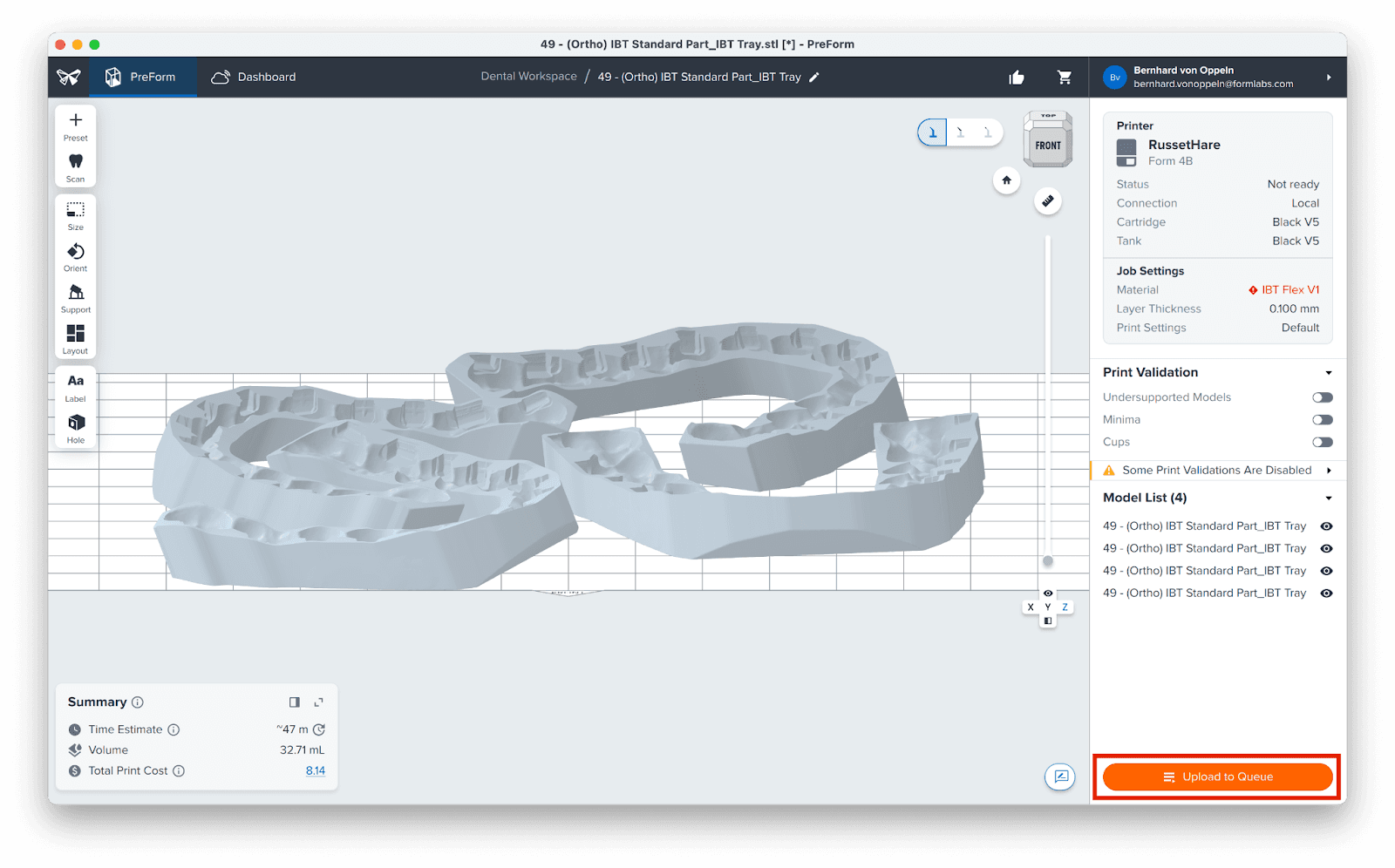
In the Job Setup menu on the right side, click the printer box to select your printing material.
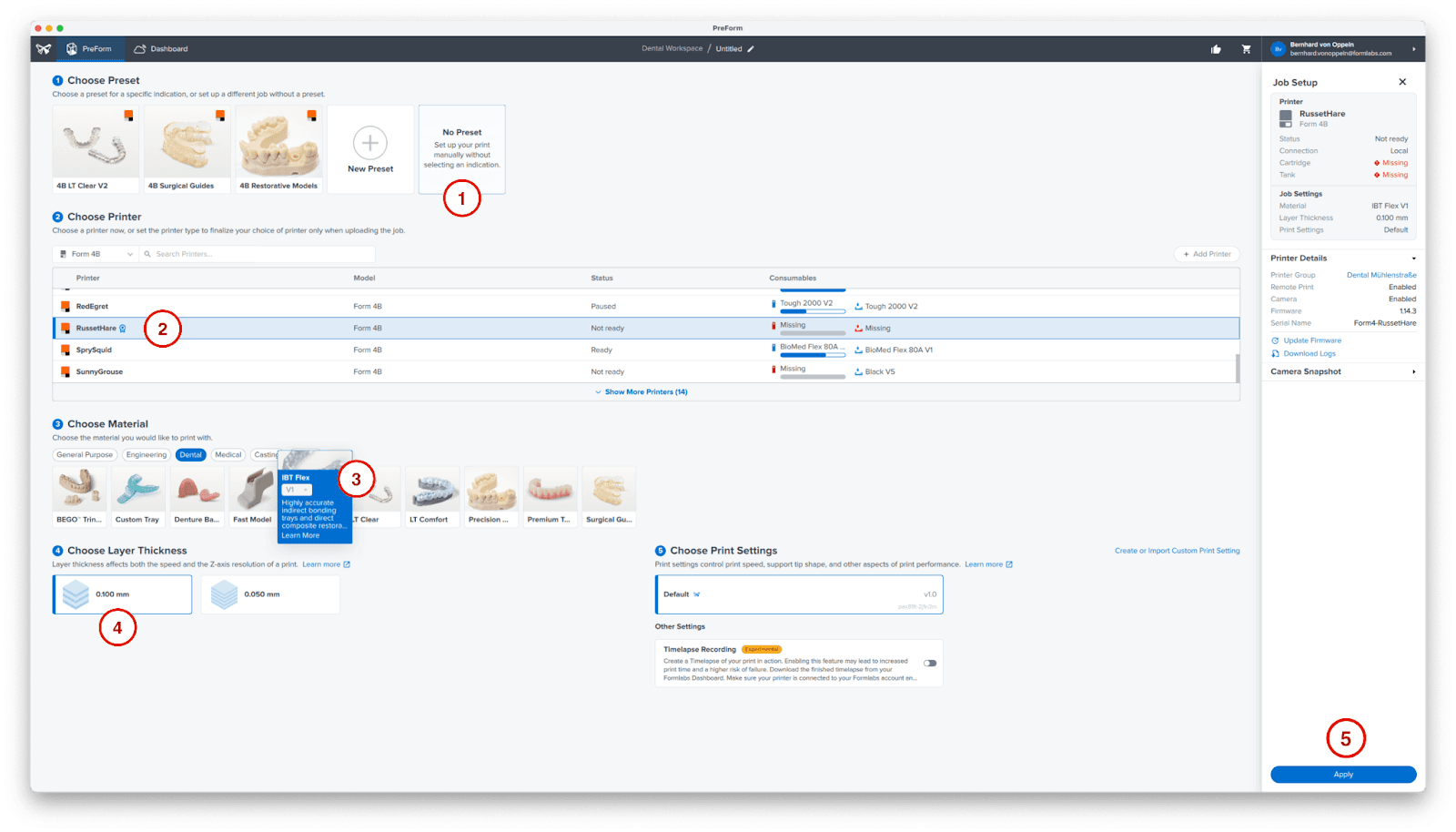
Do not use a predefined Preset (1), as PreForm does not offer one for IBT Flex bonding trays.
Select your printer (2). Under Choose Material, select IBT Flex Resin (3) and the desired layer thickness.
For IBT Flex bonding trays, 0.1 mm layer thickness (4) works well. You may choose 0.05 mm for finer details.
Click Apply (5) to finalize your job setup.
4.2 Orientation
For appliances designed with the bar-type design, the bottom surface can be adhered directly to the build platform.
Note:
Offset-type bonding trays need to be placed on supports. In this case, try to align your tray parallel to the build plate or at an angle below 40°. Please refer to this playlist on our YouTube channel to learn how to add supports to your model.
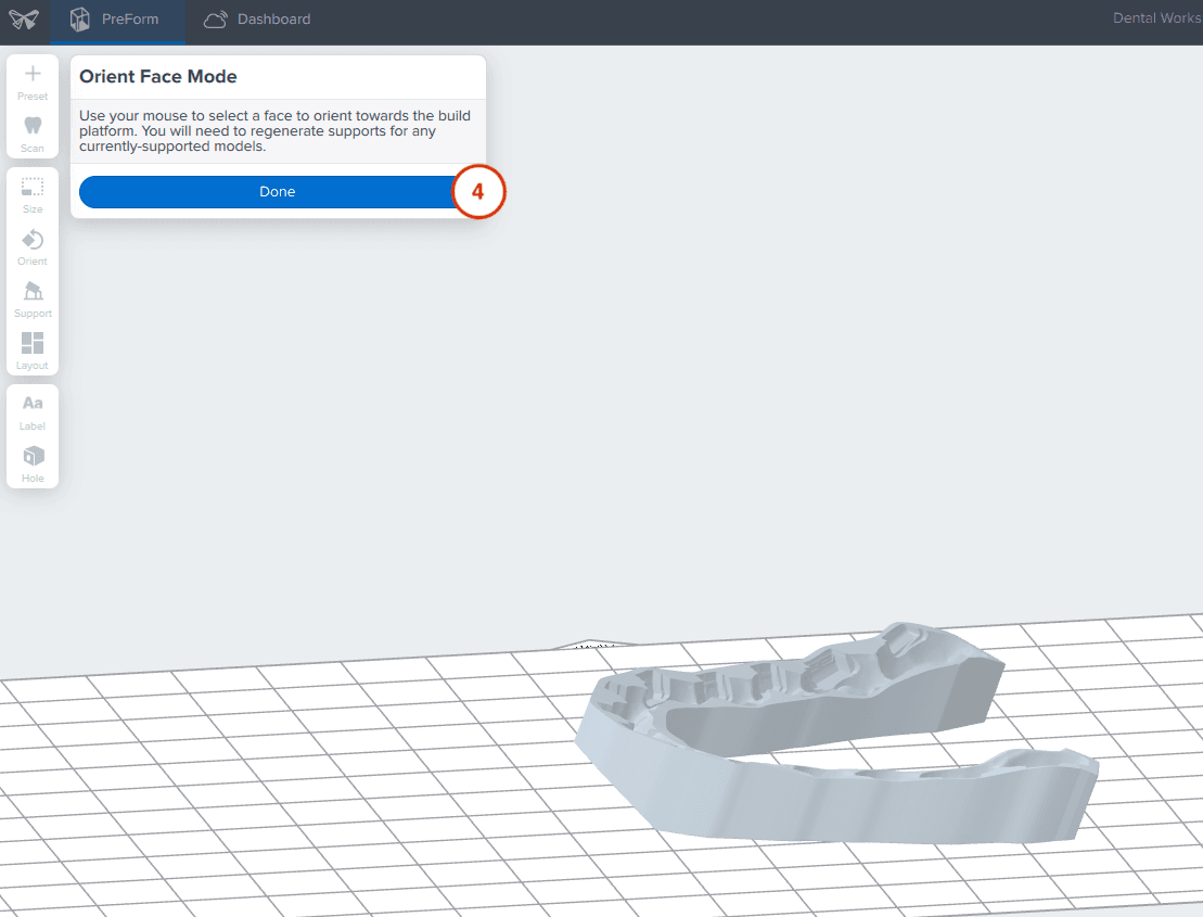
Open the Orientation tool (1) and click the Select Base (2) button.
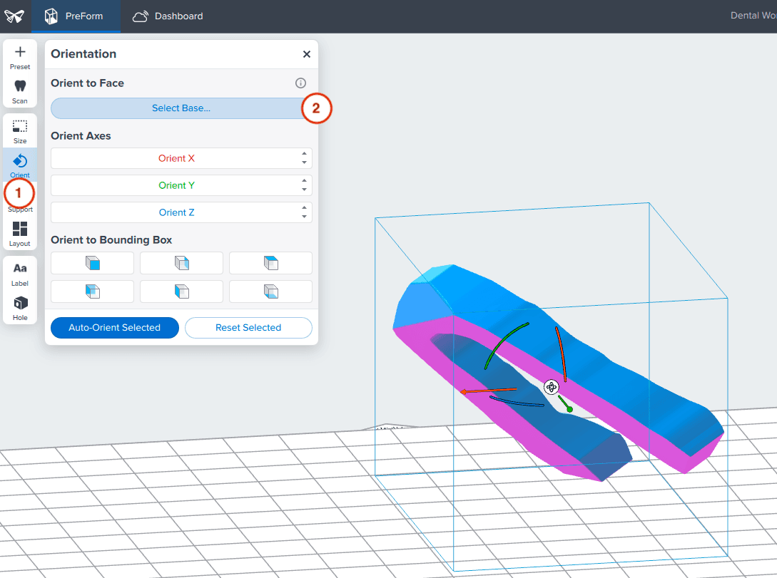
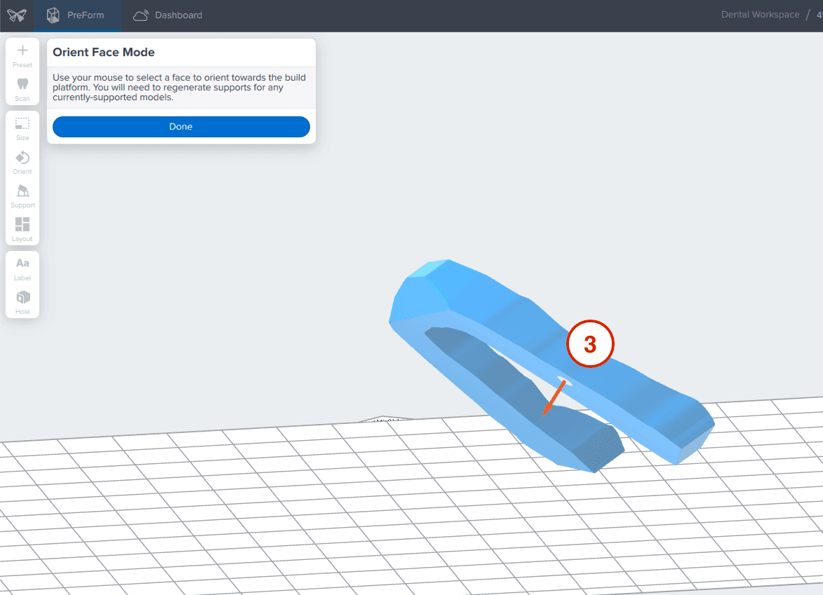
Next, click the bottom surface (3) of the part to adhere it to the build platform and confirm by clicking Done (4).
If you need to print multiple trays, add them all to your job. Ensure they are placed on the build plate without overlapping. The Layout All tool under PreForm's Layout menu can simplify this arrangement process.
Note:
If you are using supports for your bonding trays, you may overlap the support rafts if you leave space between the trays themselves.
4.3 Transferring the Job to the Printer
Once the layout is complete, the job is ready to send to the printer. Send the job to the printer by clicking Print Now. If your printer is not ready to print, the button will change to Upload to Queue, and will start printing once you have prepared your printer.
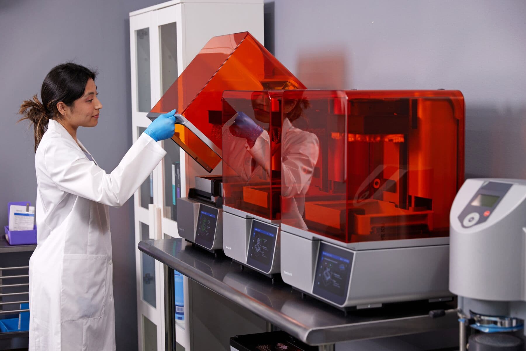
4.4 Set up the Printer
Shake the IBT Flex Resin cartridge and then insert the cartridge, a build platform, and a compatible resin tank into the Formlabs 3D printer.
Begin printing by selecting the print job from the printer’s touchscreen.
Follow any prompts or dialogs shown on the printer screen.
The printer will automatically complete the print.
Note:
For full compliance and biocompatibility, IBT Flex Resin requires a dedicated resin tank, build platform, Form Wash, and Finish Kit, which should not be mixed with any other resins.
5. Post-Processing
Always use gloves when handling uncured resin and parts.
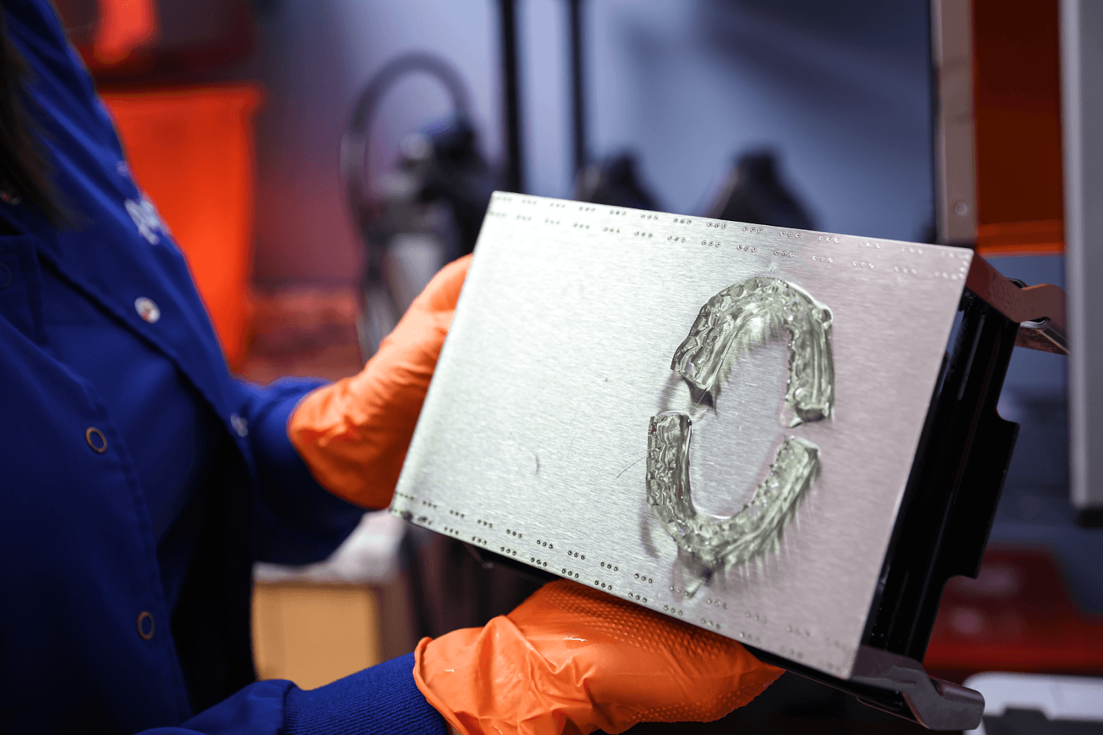
5.1 Part Removal
Remove printed parts from the build platform by wedging the Part Removal tool or a spatula under the part and rotating the tool.
Note:
Due to the flexibility of parts printed with IBT Flex Resin, they might not be released as easily as other, more rigid materials when using the Flex Build Platform.
5.2 Washing
Precautions:
When washing the printed part with solvent, ensure a properly ventilated environment and use protective masks and gloves.
Expired or unused IBT Flex Resin shall be disposed of in accordance with local regulations.
Place printed parts in a Form Wash or Form Wash L filled with isopropyl alcohol (IPA, ≥99%) and wash them for the time established in the Manufacturing Guide.
Make sure the parts are fully submerged in IPA when washing.
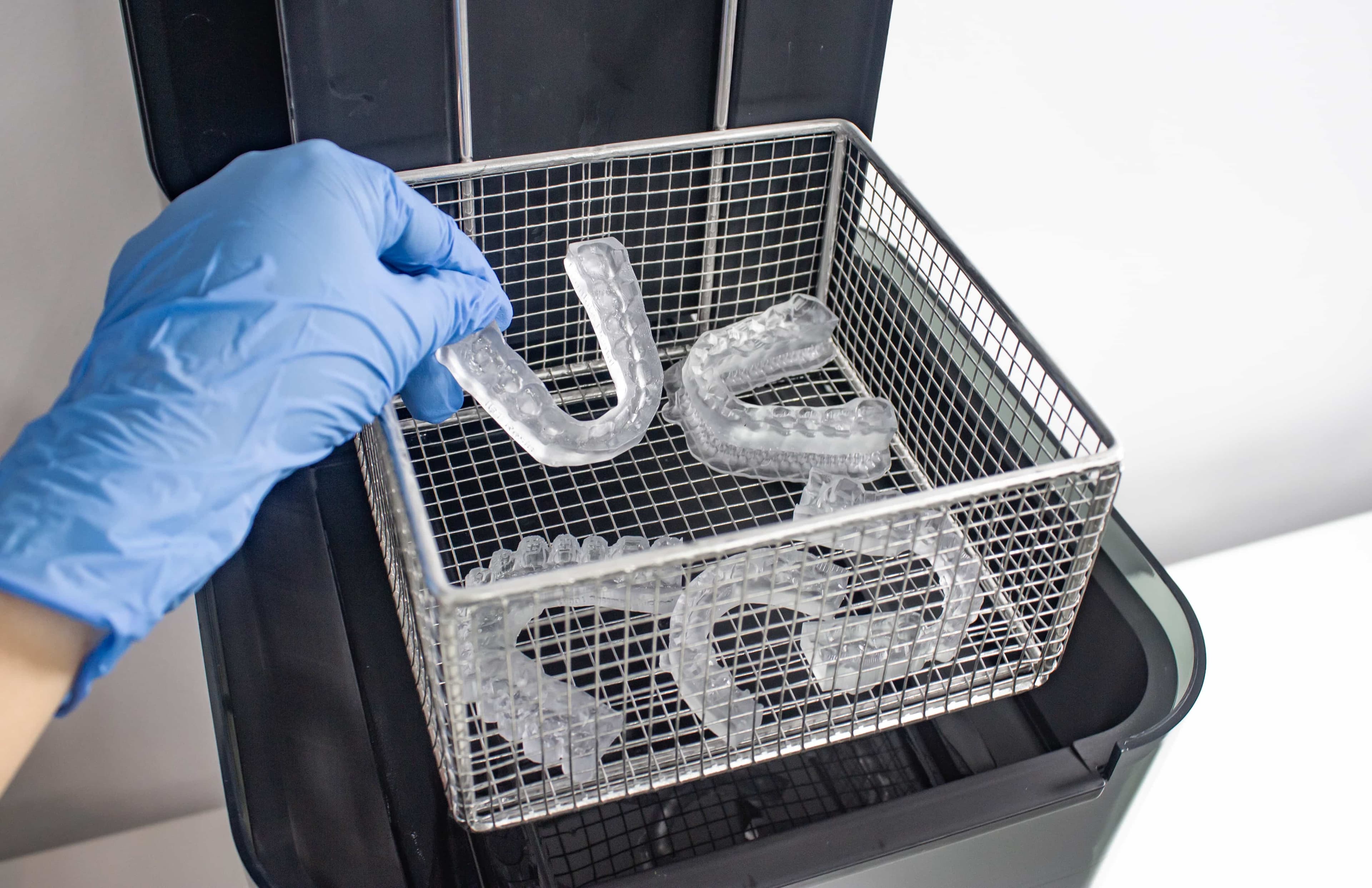
If your part geometry traps residual resin, it may be beneficial to lightly swish a paintbrush back and forth along the bracket pockets midway through the wash cycle.
Exceeding wash duration may affect dimensional accuracy and performance of printed parts over time.
Watch this video to learn how to properly wash your IBT Flex Resin bonding tray.
5.3 Drying
Remove parts from IPA and leave to air dry at room temperature for at least 30 minutes in a well-ventilated area.
Compressed air can be used to help dry parts and allow for rapid inspection of unwashed resin. Still allow time for sufficient bench drying if using compressed air.
Inspect printed parts to ensure that parts are clean and dry. No residual alcohol, excess liquid resin, or residue particles must remain on the surface before proceeding to subsequent steps.
If any wet, uncured resin is still present after drying, use a squeeze bottle with fresh IPA to remove the uncured resin. Lightly swishing a paintbrush back and forth along the bracket pockets may also help with the removal of uncured resin. After removal, dry the parts again. The use of compressed air allows for rapid inspection.
5.4 Post-Curing
To maintain dimensional accuracy and biocompatibility, specific post-curing instructions must be followed.
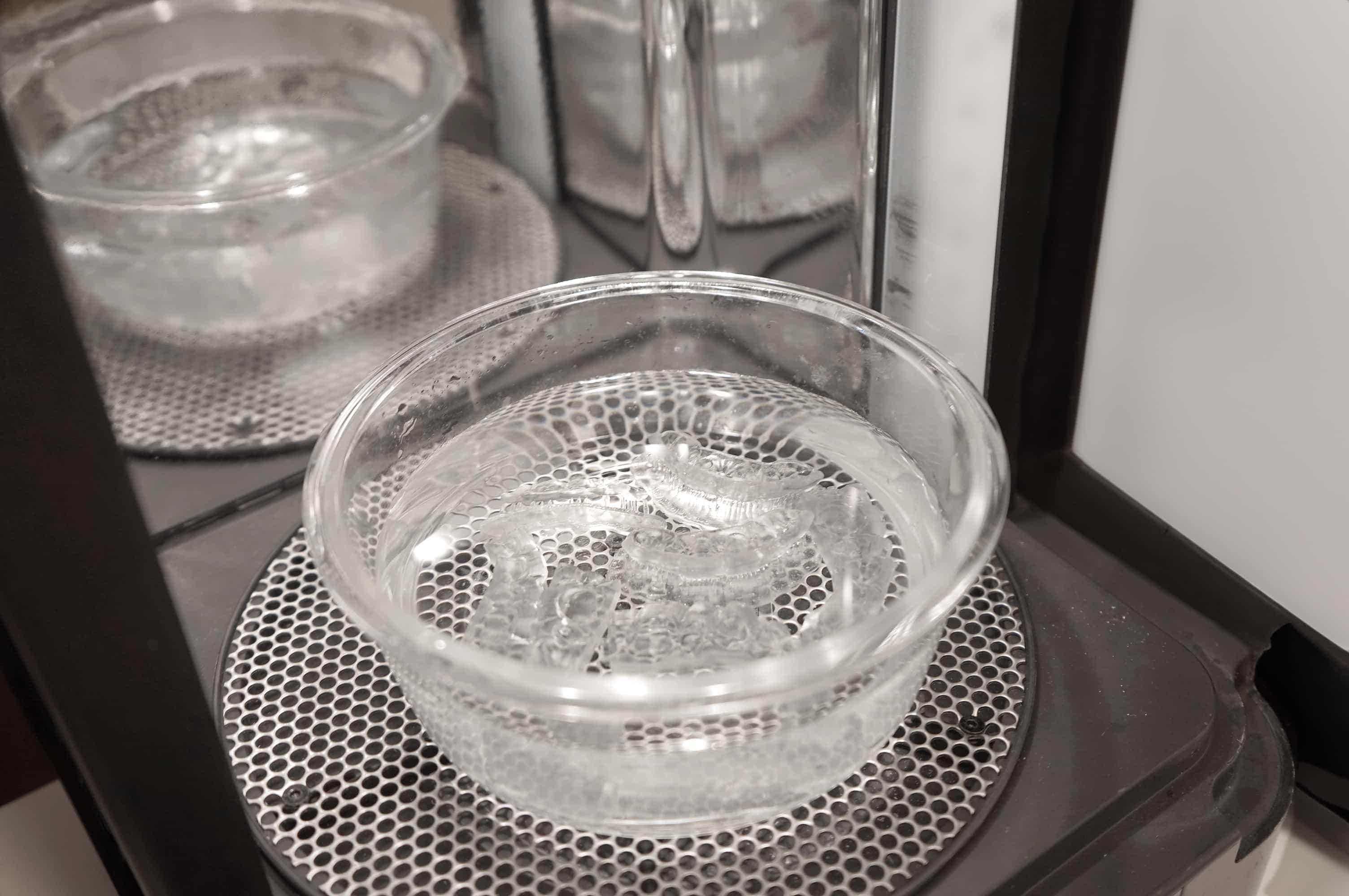
Printed parts should be cured while submerged in a transparent, water-filled container inside a Form Cure using the settings established in the Manufacturing Guide.
If indirect bonding trays are printed with rafts and supports, place printed parts in the Form Cure with the raft side down. If the trays are printed directly on the build platform without supporting structures, place the part in the Form Cure with the intaglio surface of the appliance facing up.
5.5 Support Removal
If supports were used, remove the supports using the clippers provided in the Formlabs Finish Kit, or scissors.
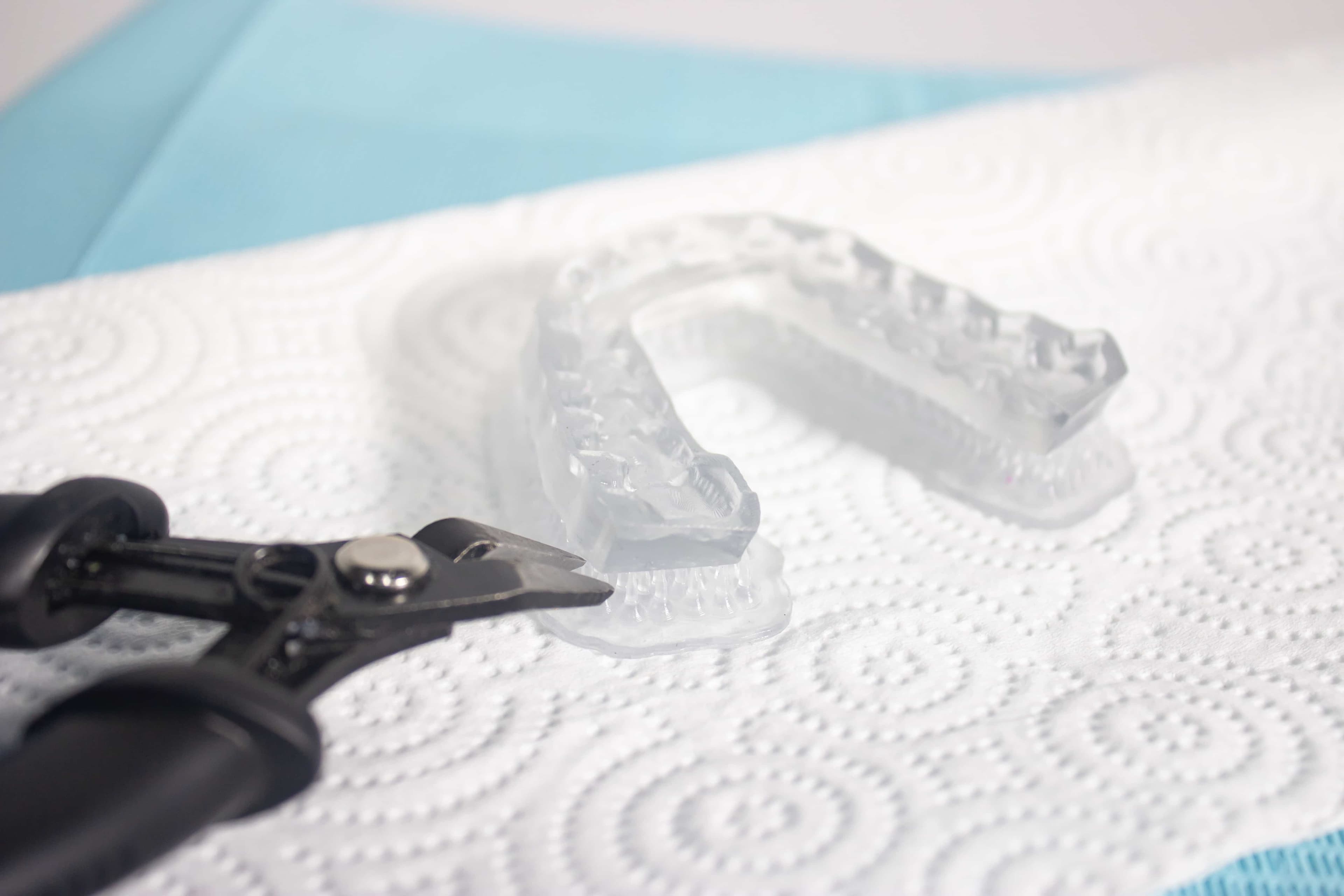
5.6 Finishing
After support removal, if any support structures are left on the surface of the 3D printed indirect bonding tray, you can remove them with a set of sharp Iris scissors.
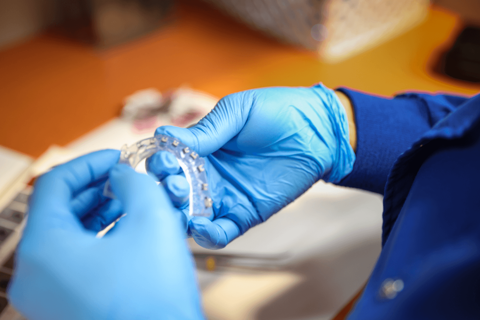
Inspect the appliance. Discard and reprint it if any damage or cracks are detected.
6. Appliance Care and Use
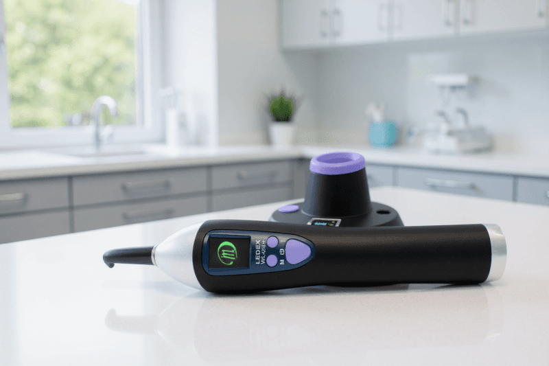
6.1 UV Cure Light Recommendation
While working with orthodontists, we found having the right UV curing light greatly improves the adhesion of the brackets through the indirect bonding tray. A fairly affordable, high-powered light we recommend is the Ledex WL-090+ Curing Light.
6.2 Cleaning
Fully post-processed parts can be cleaned using neutral soap and room temperature water.
After cleaning, always inspect parts for any cracks. Discard if any damage or cracks are detected.
6.3 Disinfection
The indirect bonding tray may be cleaned and disinfected according to facility protocols.
Our tested method of disinfection involves soaking the finished indirect bonding tray in fresh 70% IPA for five minutes.
Note:
Do not leave the part in the alcohol solution for longer than five minutes.
After disinfection, inspect the part for cracks to ensure the integrity of the indirect bonding tray.
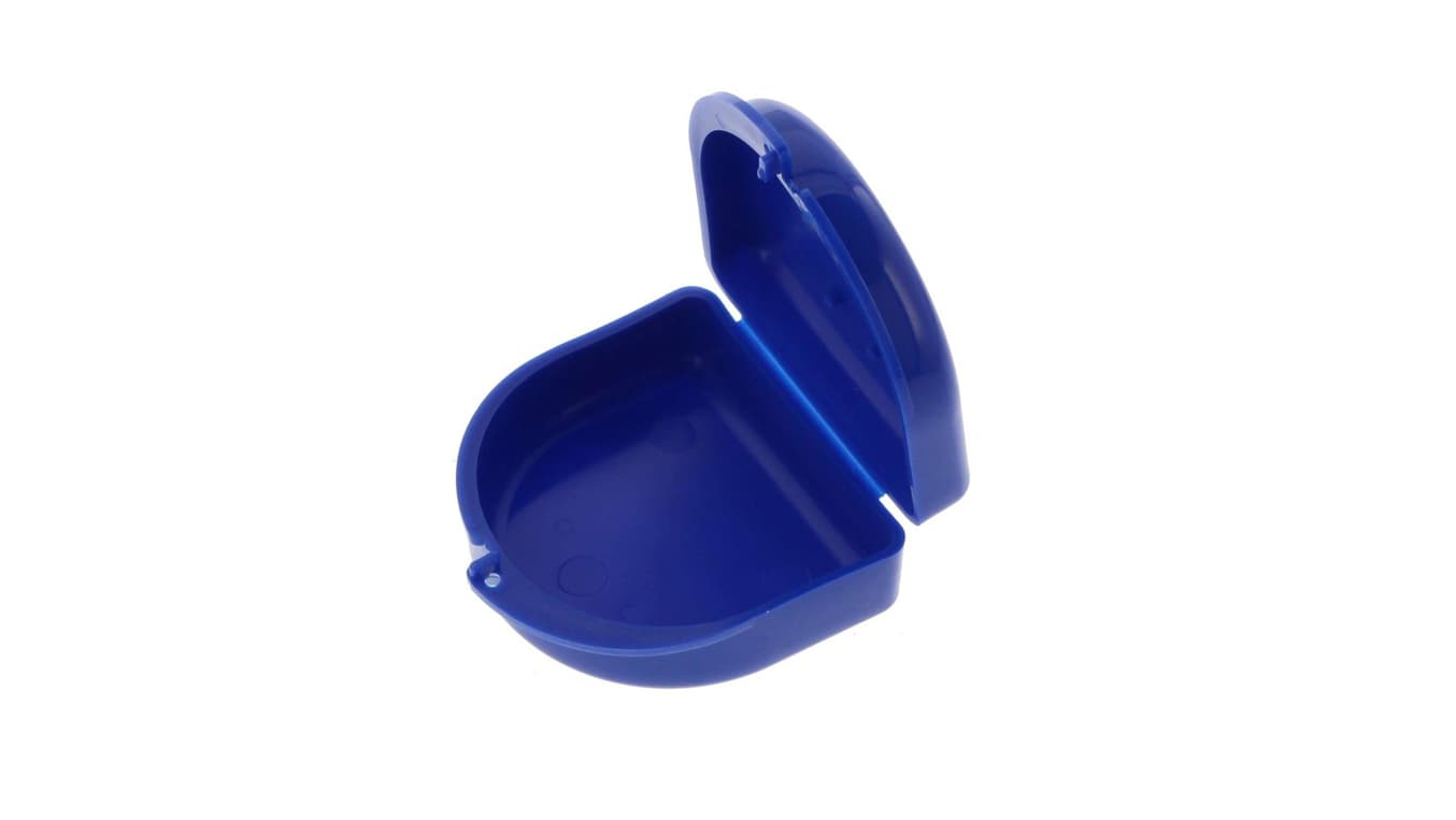
6.4 Storage
When not in use, place printed parts in closed, opaque or amber containers.
Store in a cool, dry place out of direct sunlight. Excess light exposure over time may affect the color and performance of printed parts.
Store the cartridges at 10–25 °C (50–77 °F). Do not exceed 25 °C (77 °F) when in storage. Keep away from ignition sources.
6.5 Disposal
1. Any cured resin is non-hazardous and may be disposed of as regular waste.
Follow facility protocols for waste that may be considered biohazardous.
2. Liquid resin should be disposed of in accordance with government regulations (community, regional, national).
Contact a licensed professional waste disposal service to dispose of liquid resin.
Do not allow waste to enter storm or sewer drainage systems.
Avoid release into the environment.
Dispose of contaminated packaging as unused product.
Additional Resources
Explore Formlabs dental resources for in-depth guides. step-by-step tutorials, white papers, webinars, and more.
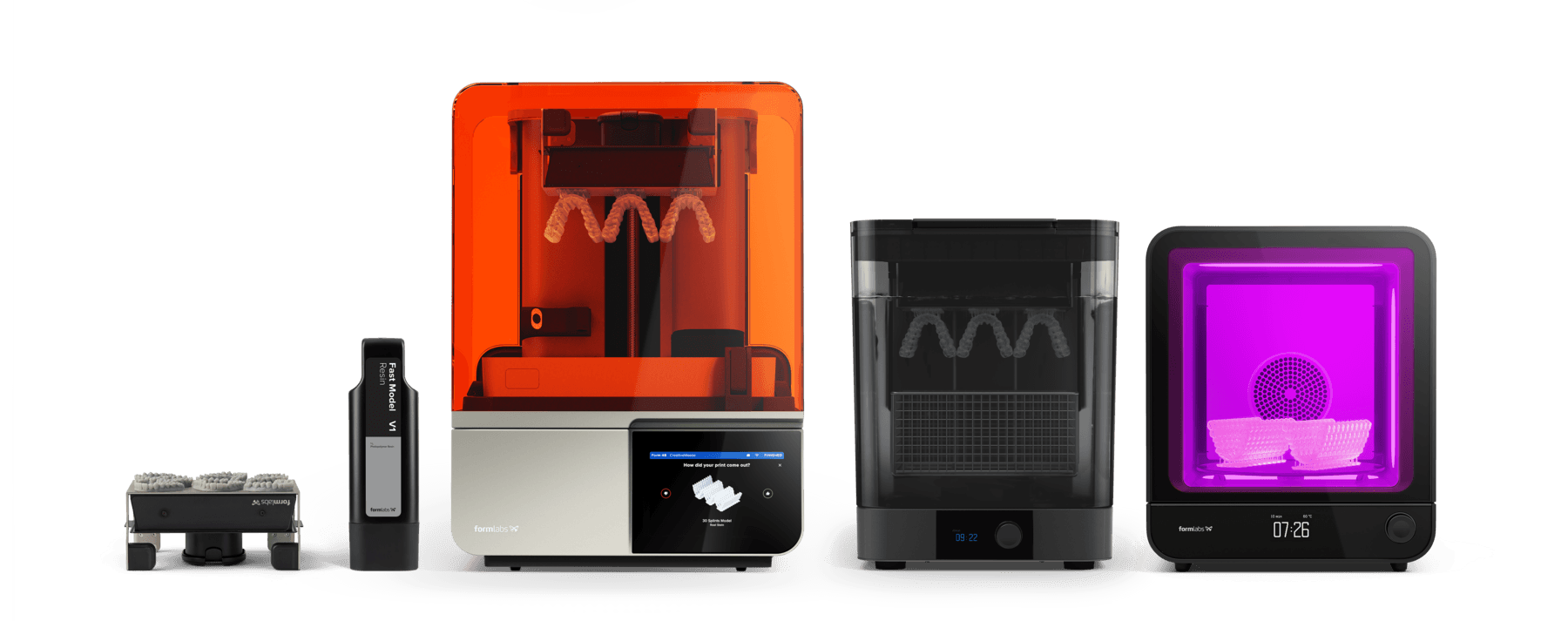
Dentistry Made Easier
Form 4B is a blazing fast dental 3D printer that offers the most diverse materials library for dentistry and orthodontics. Create high-quality dental models and biocompatible appliances fast, with easy workflows, leading reliability, and stunning part quality using the Form 4B ecosystem.